
Open-close type current and voltage transformer

A technology of current transformer and voltage transformer, applied in the direction of inductors, transformers, transformer/inductor coils/windings/connections, etc., can solve the accuracy requirements that cannot guarantee the measurement, unreliable contact at the iron core connection, and affect the measurement. Current accuracy and other issues, to achieve the effect of good magnetic circuit closure, good contact reliability, and meeting the measurement accuracy requirements

Inactive Publication Date: 2012-02-22
DALIAN UNIV OF TECH
View PDF6 Cites 10 Cited by
  • Summary
  • Abstract
  • Description
  • Claims
  • Application Information

AI Technical Summary

Problems solved by technology

[0003] 1. It is inconvenient to install when the feed-through current transformer takes the voltage signal
[0004] 2. The open-close current transformer is easy to install, but it is necessary to add a voltage transformer when the voltage signal is used
[0005] 3. The contact of the iron core connection of the split-type transformer is unreliable, and it cannot be guaranteed that the connection meets the measurement accuracy requirements during installation.
[0006] 4. In the existing split-type transformer, only half of the iron core is provided with windings, which affects the accuracy of the measured current

Method used


Image

  • Open-close type current and voltage transformer
  • Open-close type current and voltage transformer
  • Open-close type current and voltage transformer

Examples


Embodiment Construction

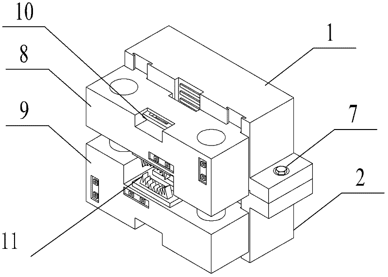
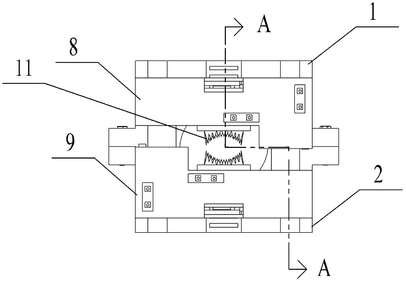
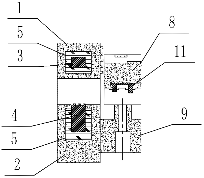
[0035] The present invention will be further described below in conjunction with the accompanying drawings. Such as Figure 1-9 As shown, a split current and voltage transformer includes a current transformer and a voltage sampler, and the voltage sampler is installed on one side of the current transformer through a T-shaped protrusion and a T-shaped slot on the side of the current transformer. side, and determine the relative position between the current transformer and the voltage sampler through the two fixed pieces 10 and the protrusions on the current transformer;

[0036] The current transformer includes a housing, an iron core and a secondary winding 5. The housing is two upper and lower parts with the same structure and can be opened and closed, that is, the upper housing 1 and the lower housing 2. The iron cores described above are two C-shaped iron cores with the same structure, that is, the upper iron core 3 and the lower iron core 4; the upper iron core 3 and the ...


PUM


Abstract

The invention discloses an open-close type current and voltage transformer which comprises a current transformer and a voltage sampler, wherein the voltage sampler is mounted on one side of the current transformer through a T-shaped bulge and a T-shaped groove on the side surface of the current transformer, and the relative positions of the current transformer and the voltage sampler can be determined through two fixing pieces and the bulge on the current transformer. As an upper housing and a lower housing of the current transformer comprise mounting holes which can be fastened by using nuts and screw rods, thereby being convenient to enable the upper housing and the lower housing to form a closed combined whole during the use. The whole current and voltage transformer can be combined by adopting the screw rods and the nuts, thereby simultaneously having the function of sampling voltage signals. A groove structure is adopted at the joint of two C-shaped iron cores and matched with a resin housing with orthogonal grooves, the connection is reliable, the good closing of a magnetic circuit is ensured and the requirements on the measurement precision can be met.

Description

technical field [0001] The invention relates to a current and voltage detection device of a power system, in particular to a split current and voltage transformer. Background technique [0002] Current transformers and voltage transformers are used for current and voltage detection in power systems. They have the functions of electrical isolation and voltage-current conversion, and have a wide range of applications. Chinese patent ZL 200810074348 discloses a feed-through current transformer that is convenient for taking voltage, and the method is to directly take the voltage signal by piercing the insulation layer of the wire. Chinese patent ZL 200820124089 discloses a split-type transformer, which has a split-type transformer core, and the joint of the iron core is in the shape of a tooth. Chinese patent ZL 200910222101 also discloses a magnetic circuit open-close current transformer, in which the joints of the iron cores of the open-close transformer have a single-row zig...

Claims


Application Information

Patent Timeline
Patent Type & Authority Applications(China)
IPC IPC(8): H01F38/34H01F38/30H01F27/30H01F38/26G01R15/18
Inventor 牟宪民李冠林陈希有
Owner DALIAN UNIV OF TECH
Learn More