Wire winding machine for annular coil

A technology of toroidal coils and winding machines, which is applied in coil manufacturing and other directions, can solve problems such as troublesome and laborious, and affect coil production efficiency, and achieve the effects of convenient operation, shortened auxiliary man-hours, and simple operation

Active Publication Date: 2012-02-22
TIANJIN BINHAI ELECTRICAL EQUIP
View PDF5 Cites 26 Cited by
  • Summary
  • Abstract
  • Description
  • Claims
  • Application Information

AI Technical Summary

Problems solved by technology

The operation of the adjustment part of the above-mentioned thread storage ring slit is also troublesome and laborious. Each adjustment needs to move two parts to open or close the thread storage ring, which affects the production efficiency of the coil

Method used


Image

  • Wire winding machine for annular coil
  • Wire winding machine for annular coil
  • Wire winding machine for annular coil

Examples


Embodiment Construction

[0031] In order to further understand the content, features and effects of the present invention, the following embodiments are given as examples, and detailed descriptions are as follows with accompanying drawings:

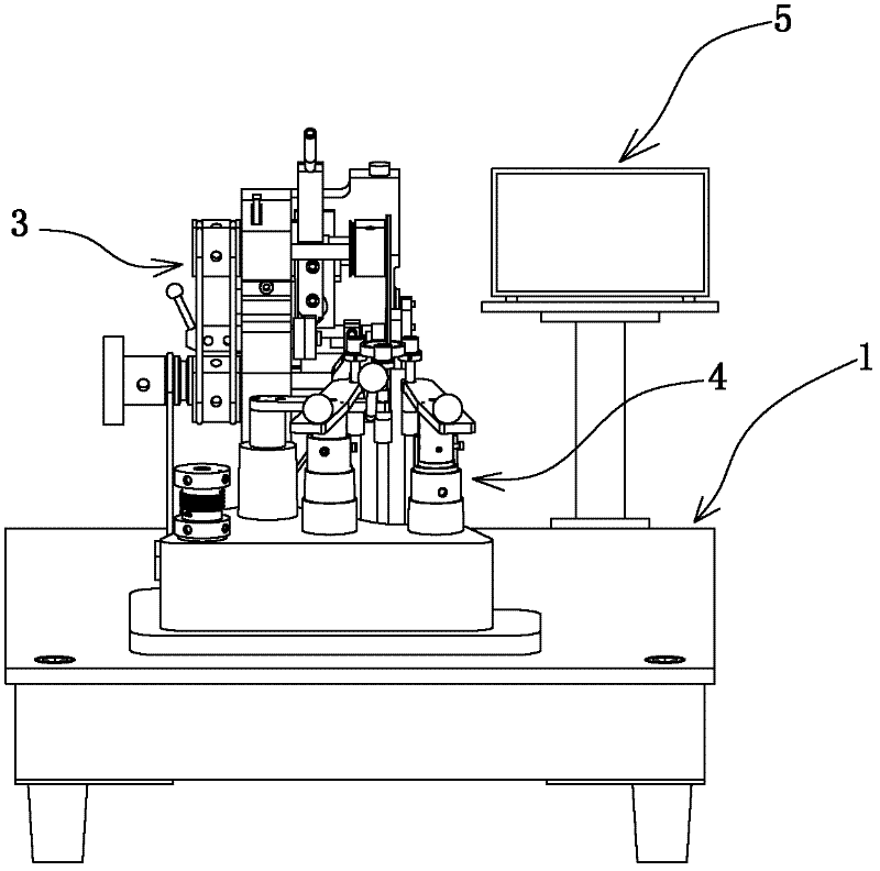
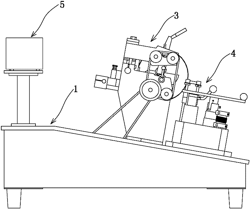
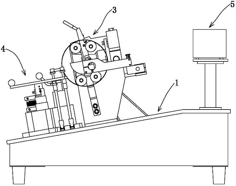
[0032] See Figure 1-13 , A toroidal coil winding machine, consisting of a workbench 1, a motor 2 arranged at the lower end of the workbench, a winding actuator 3, a coil clamping mechanism 4, and an electrical control part 5 arranged on the workbench. The motor transmits the power to the winding execution structure and the coil clamping mechanism through the transmission mechanism, and drives the wire storage ring and the coil core to rotate respectively, and winds the copper wire wound on the wire storage ring on the coil core, and finally makes Loop coil.

[0033] The above-mentioned winding execution structure includes a bracket 3-1 fixedly mounted on the workbench, a wire storage ring 3-2, and a supporting part 3-3 that is mounted on the bracket and includes sev...


PUM


Abstract

The invention relates to a wire winding machine for an annular coil. The wire winding machine for the annular coil consists of a working platform, a motor, a wire winding actuating mechanism, a coil clamping mechanism and an electric appliance control part, wherein the wire winding actuating mechanism consists of a bracket, a wire storing ring, a supporting part, a slotting adjusting part and a pressing part; and the coil clamping mechanism consists of three clamping shafts which are uniformly distributed along a circumference, a clamping shaft opening and closing mechanism and a clamping sleeve. The wire winding machine for the annular coil is characterized in that the bracket consists of an upper bracket and a lower bracket which are rotationally connected; the slotting adjusting part consists of a first split and a second split which are respectively mounted on the upper bracket and the lower bracket; and the clamping shaft opening and closing mechanism comprises an opening actuating mechanism consisting of a driving shaft and a supporting arm, and a resetting mechanism consisting of a resetting shaft and a torsion spring. Compared with the prior art, the wire winding machine for the annular coil has the advantages that the opening and closing of the wire storing ring are realized by adjusting the second handle of the second split, two-step operation is simplified into one-step operation, the opening of the clamping shafts is realized by tightly holding a handle on the supporting arm, and bidirectional adjustment is simplified into unidirectional adjustment. Thus, the wire winding machine has the characteristics that operation is convenient, time is saved and production efficiency is improved.

Description

Technical field [0001] The invention relates to a coil winding machine, in particular to a toroidal coil winding machine with convenient operation and high production efficiency. Background technique [0002] The toroidal coil winding machine is a kind of equipment suitable for winding and processing toroidal coils such as various toroidal transformers, magnetic toroidal inductors, and mutual inductors. At present, there are toroidal coil winding machines with various structures on the market. Among them, the side-slip toroidal special frequency conversion winding machine produced by Liqun International Industrial Co., Ltd. consists of a workbench, a motor set at the lower end of the workbench, and a workbench. The winding actuator, the coil clamping mechanism and the electrical control part are composed. The winding actuator is composed of a bracket fixed on the workbench, a slotted thread storage ring, a thread storage ring support part, a thread storage ring slit adjustment p...

Claims


Application Information

Patent Timeline
Patent Type & Authority Applications(China)
IPC IPC(8): H01F41/08
Inventor 曾凡岭李茂永崔永宽刘巨胜
Owner TIANJIN BINHAI ELECTRICAL EQUIP
Why Eureka
Try Eureka