
Horizontal-shaft tidal turbine with linkage spiral vanes

A spiral and tidal current energy technology, which is applied in mechanical equipment, hydroelectric power generation, ocean energy power generation, etc., can solve problems such as failure to enter the practical stage, damage to the marine environment, and late start of research on oscillating hydrofoils.

Active Publication Date: 2016-07-06
HOHAI UNIV
View PDF7 Cites 11 Cited by
  • Summary
  • Abstract
  • Description
  • Claims
  • Application Information

AI Technical Summary

Problems solved by technology

According to the structural classification, the existing tidal energy turbines mainly include horizontal axis turbines, vertical axis turbines and oscillating hydrofoils. These tidal energy turbines have their own advantages and disadvantages. Horizontal axis turbines have relatively mature technology and high energy harvesting efficiency, but serious yaw loss ; Although the structure of the vertical axis turbine is simple and easy to maintain, it still has the problems of difficult self-starting and low efficiency; the research on the oscillating hydrofoil started relatively late and is still in the exploratory stage
At the same time, the vibration and noise of these water turbines are large, which has a certain degree of impact and damage on the marine environment on which marine organisms such as fish and cephalopods depend.
Judging from the published patented technology, it is also impossible to enter the practical stage due to the aforementioned deficiencies
[0004] Chinese patent application 201210556394.X discloses a "compound tidal energy vertical axis turbine". Although this scheme adopts an external H-shaped structure and an internal S-shaped structure, it has the advantages of fast start-up performance and good stability. Direction arrangement makes the whole machine less efficient and has a greater impact on marine life
Chinese patent application 201310291232.2 discloses "a tidal current energy harvesting turbine with variable blade posture". Too complex, poor economy, no practical value

Method used

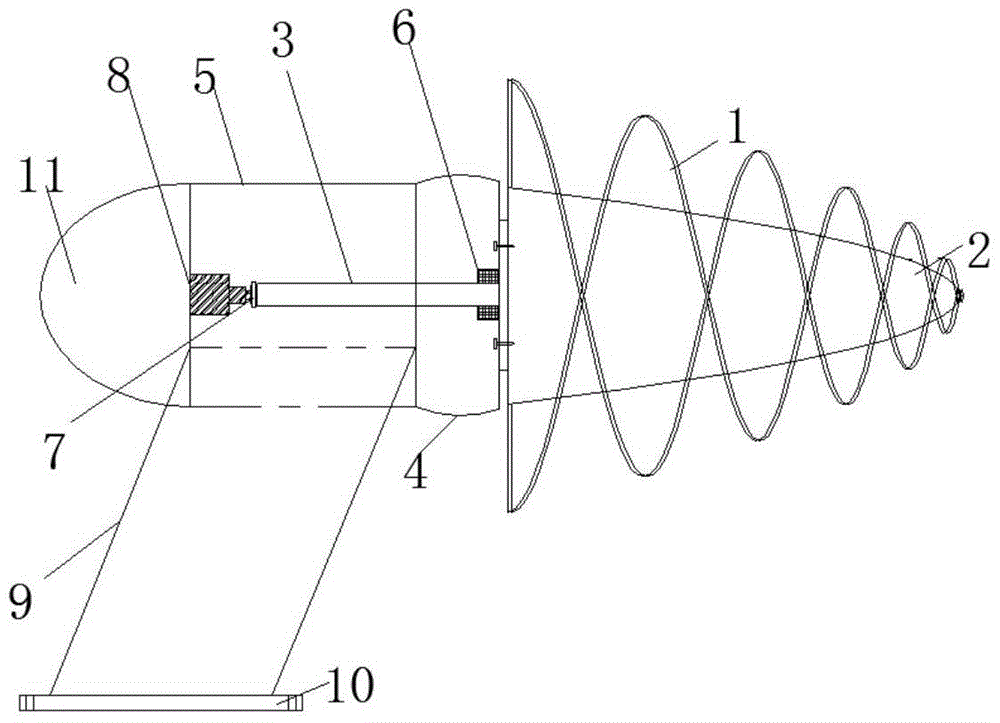
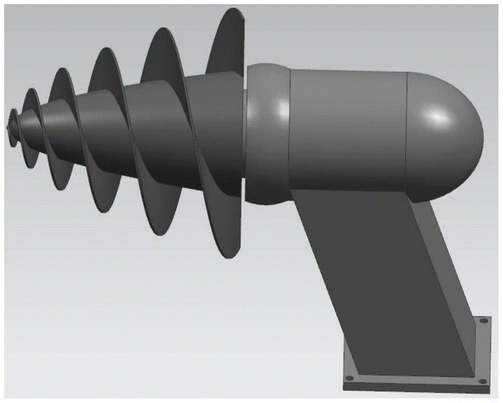
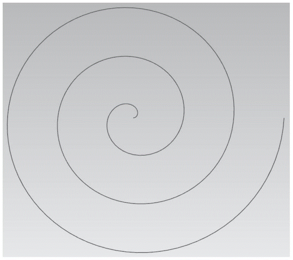

Image

  • Horizontal-shaft tidal turbine with linkage spiral vanes
  • Horizontal-shaft tidal turbine with linkage spiral vanes
  • Horizontal-shaft tidal turbine with linkage spiral vanes

Examples


Embodiment 1

[0096] The design scheme of embodiment 1 is exactly the same as the above-mentioned technical scheme of the present invention, and the design parameters of its main components are disclosed as follows:

[0097] The quantity of interlocking helical blade (1) of the present invention is 2 pieces; The sectional shape of interlocking helical blade (1) is selected symmetrical airfoil; The height of interlocking helical blade (1) is 310cm, maximum diameter is 200cm, The minimum pitch is 85cm, and the pitch gradient ratio is 5:6; the height of the conical hub (2) is 310cm, and the maximum diameter is 105cm; the height of the water guide cone (11) is 180cm, and the diameter is 105cm.

Embodiment 2

[0098] The design scheme of embodiment 2 is exactly the same as the above-mentioned technical scheme of the present invention, and the design parameters of its main components are disclosed as follows:

[0099] The quantity of interlocking helical blade (1) of the present invention is 1 piece; The cross-sectional shape of interlocking helical blade (1) selects asymmetric airfoil; The height of interlocking helical blade (1) is 320cm, maximum diameter is 205cm, The minimum pitch is 85cm, and the pitch gradient ratio is 5:6; the height of the conical hub (2) is 320cm, and the maximum diameter is 105cm; the height of the water guide cone (11) is 190cm, and the diameter is 105cm.

Embodiment 3

[0100] The design scheme of embodiment 3 is exactly the same as the above-mentioned technical scheme of the present invention, and the design parameters of its main components are disclosed as follows:

[0101] The present invention is 5 pieces to the quantity of interlocking spiral blade (1); The cross-sectional shape of interlocking spiral blade (1) is selected symmetrical airfoil; The height to interlocking spiral blade (1) is 320cm, and the maximum diameter is 185cm, the minimum pitch is 90cm, and the pitch gradient ratio is 5:6; the height of the conical hub (2) is 320cm, and the maximum diameter is 105cm; the height of the water guide cone (11) is 160cm, and the diameter is 105cm.

[0102] The specific application process of the present invention is: the runner of the present invention includes interlocking helical blades (1) and the hub (2) along the conical hub (2). (1), the energy of the tidal current is converted into the kinetic energy of the runner by the interlock...


PUM

PropertyMeasurementUnit
Heightaaaaaaaaaa
The maximum diameteraaaaaaaaaa
Heightaaaaaaaaaa

Abstract

The invention relates to a horizontal-shaft tidal turbine with linkage spiral vanes. The horizontal-shaft tidal turbine comprises a spindle, a case, a thrust bearing, a coupling, a generator, a rack, a base and a water guide cone, wherein the lower side of the case is respectively supported by the rack and the base; the horizontal-shaft tidal turbine is characterized by further comprising linkage spiral vanes in two-dimensional linkage spiral line shape, a cone-like-shaped hub immersing into tide, and a sealing cover; the generator is connected with the spindle and the cone-like-shaped hub by the coupling, the sealing cover is arranged at the junction of the spindle and the cone-like-shaped hub, the water guide cone is arranged at the tail part of the case at the rear side of the cone-like-shaped hub; and the linkage spiral vanes rotate at uniform speed at the periphery of the cone-like-shaped hub by forming gradient stretching along the axial direction of the cone-like-shaped hub to form a spatial warping shape to be uniformly distributed via the thrust bearing. The horizontal-shaft tidal turbine can greatly reduce hydraulic friction collision and reduce loss at the entrance head, thus improving the capacitation effect of the water turbine and well solving the difficulty of allowing ocean fish schools to smoothly pass.

Description

technical field [0001] The invention belongs to the technical field of water turbine power generation, in particular to a horizontal axis tidal current energy water turbine with interlocking spiral blades. Background technique [0002] In recent years, with increasing attention to marine resources and marine rights and interests, human exploration and development of tidal current energy is gradually heating up. As an important part of ocean energy, tidal current energy has predictability, high power density and energy stability. Outstanding advantages, development and utilization have attracted much attention. [0003] The development of tidal current energy is mainly concentrated in the field of power generation technology, and the tidal current energy turbine is its core energy conversion device. According to the structural classification, the existing tidal energy turbines mainly include horizontal axis turbines, vertical axis turbines and oscillating hydrofoils. These t...

Claims


Application Information

Patent Timeline
IPC IPC(8): F03B13/26F03B3/04F03B3/12
CPCF03B3/04F03B3/121F03B3/126F03B13/26Y02E10/20Y02E10/30
Inventor 阚阚郑源付士凤何中伟陈会向芦月陈荣杰
Owner HOHAI UNIV
Learn More