Cooling system

A cooling system and fan technology, which is applied to engine cooling, coolant flow control, fluid pressure actuation system components, etc. Working time, avoiding overheating and undercooling, the effect of improving the efficiency ratio

Inactive Publication Date: 2014-01-15
SHAANXI SHENGMAI PETROLEUM
View PDF0 Cites 9 Cited by
  • Summary
  • Abstract
  • Description
  • Claims
  • Application Information

AI Technical Summary

Problems solved by technology

[0002] At present, most of the cooling fans in the engine cooling system of construction machinery are driven by the engine crankshaft, so that the cooling air passes through the radiator to take away the heat of the cooling water. This mechanical driving method makes the cooling capacity of the fan only change with the engine speed, but cannot It changes automatically with the thermal state of the engine and the ambient temperature, so it will inevitably cause serious shortage of cooling capacity at low speed and heavy load, and excessive cooling at high speed and small and medium load, which not only affects the progress of the project, but also increases Reduce fuel consumption and increase operating costs; of course, some large-scale construction machinery adopts an independent heat dissipation system, that is, the speed of the cooling fan is controlled by electro-hydraulic drive. Relief valve, the system detects the engine cool

Method used


Image

  • Cooling system

Examples


Example Embodiment

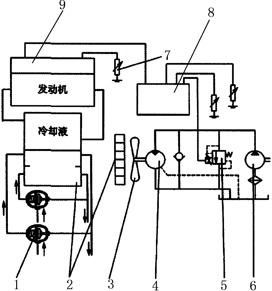
[0007] As shown in the figure, the cooling system of the present invention includes a fan 3, which is connected to a fixed-quantity motor 4, an electric proportional relief valve 5, a fixed-quantity pump 6, and an oil tank in sequence. The electric proportional relief valve 5 is also connected to the control The temperature sensor 8 and the temperature sensor 7 are connected, and the temperature sensor 7 is connected to the engine ECU 9 through the CAN bus. In addition, the front end of the fan 3 is also equipped with a radiator 2 which is connected to hydraulic oil and torque converter oil through a temperature control valve 1.

[0008] The temperature sensor 7 is connected to the controller 8 through a cable, and the temperature signal of the engine coolant is provided by the engine ECU 9 through the CAN bus. The quantitative pump 6 is connected to the oil tank through a filter, and the output shaft of the quantitative motor 4 is connected to the cooling fan 3 in the cooling dev...


PUM


Abstract

The invention relates to a cooling system used for a loading machine. The cooling system comprises a fan, wherein the fan is connected with a constant displacement motor, an electric proportional relief valve, a constant displacement pump and an oil tank in sequence, the electric proportional relief valve is further connected with a controller and a temperature sensor, the temperature sensor is connected with an engine ECU through a CAN bus, and a radiator is further arranged at the front end of the fan and connected with hydraulic oil and bending moment oil through a temperature control valve. The independent hydraulic-controlled cooling fan is adopted in the cooling system, the flow of the hydraulic oil flowing through the radiator and the flow of the bending moment oil flowing through the radiator are controlled by the temperature control valve, the hydraulic oil is matched with bending moment oil, operational use time of the fan is greatly increased, and the performance ratio of the fan is improved; meanwhile, the temperature of engine coolant, the temperature of hydraulic oil and the temperature of bending moment oil are controlled to be within the best temperature interval in the shortest time, overheating and supercooling of media are avoided, and stabilization of the thermal state of the whole machine is guaranteed.

Description

technical field [0001] The invention relates to a cooling system for a loader. Background technique [0002] At present, most of the cooling fans in the engine cooling system of construction machinery are driven by the engine crankshaft, so that the cooling air passes through the radiator to take away the heat of the cooling water. This mechanical driving method makes the cooling capacity of the fan only change with the engine speed, but cannot It changes automatically with the thermal state of the engine and the ambient temperature, so it will inevitably cause serious shortage of cooling capacity at low speed and heavy load, and excessive cooling at high speed and small and medium load, which not only affects the progress of the project, but also increases Reduce fuel consumption and increase operating costs; of course, some large-scale construction machinery adopts an independent heat dissipation system, that is, the speed of the cooling fan is controlled by electro-hydrau...

Claims


Application Information

Patent Timeline
IPC IPC(8): F01P5/04F01P7/04F04D27/00E02F9/22F15B21/04
Inventor 王耀斌
Owner SHAANXI SHENGMAI PETROLEUM
Why Eureka
Try Eureka