Transversely self-driven three-dimensional copying machining method and three-dimensional copying machine

A technology of three-dimensional profiling and processing methods, which is applied in metal processing equipment, manufacturing tools, and replication process control systems, etc., can solve the problems of inaccurate profiling size, enlargement of processing errors, large and complex overall structure of profiling machine tools, etc. Simplified structure and processing method, and the effect of high profiling accuracy

Inactive Publication Date: 2012-02-29
GUANGZHOU CIVIL AVIATION COLLEGE
View PDF5 Cites 17 Cited by
  • Summary
  • Abstract
  • Description
  • Claims
  • Application Information

AI Technical Summary

Problems solved by technology

The installation of so many power drives leads to a large and complex overall structure of the profiling machine tool; in addition, due to the discrete setting of the power devices, the processing error may be enlarged, and the profiling size is not accurate enough

Method used


Image

  • Transversely self-driven three-dimensional copying machining method and three-dimensional copying machine
  • Transversely self-driven three-dimensional copying machining method and three-dimensional copying machine
  • Transversely self-driven three-dimensional copying machining method and three-dimensional copying machine

Examples


Embodiment 1

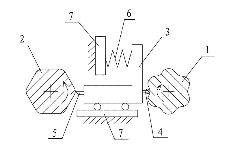
[0039] refer to figure 2 , the workpiece 2 to be processed is in the shape of a regular hexagonal prism with rounded edges, and its cross-section is a regular hexagon with rounded corners. For mold 1, the finished size of the workpiece is used as the design basis, that is, in figure 2 The size of the workpiece to be processed in 2 is regarded as the size of the standard finished product.

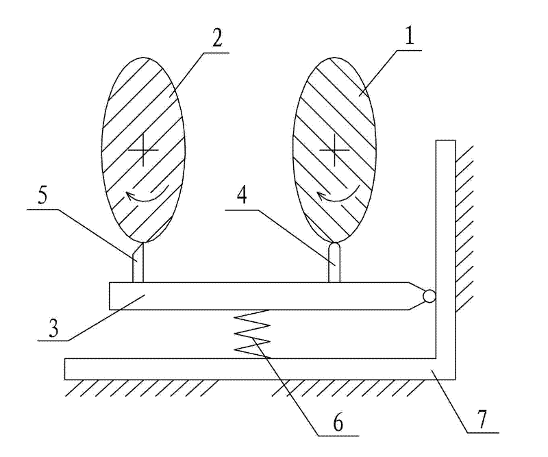
[0040]1) Prepare the profiling machine tool, adjust the profiling frame 3 of the profiling machine tool to be located between the main shaft of the profiling machine tool and the master axis, and adjust the contact 4 on the profiling frame 3 to face the direction of the profiling axis , the processing head 5 is adjusted to face the direction of the main shaft, and its specific structure is as follows figure 2 In addition, cutting processing is adopted here, so the processing head 5 is a turning tool, and the contact 4 is a roller (if the horizontal self-driven three-dimensional profilin...

Embodiment 2

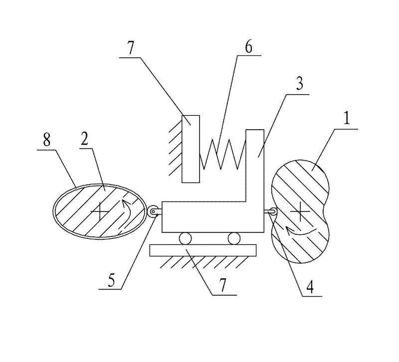
[0046] refer to image 3 , the workpiece 2 to be processed is a hollow cone part with an elliptical cross-section, because it is in the shape of a cone, it has a large end and a small end, and the central axis is coaxial with the spindle axis during installation. The cone angle of the part is 15°, the height is 50mm, the major axis of the ellipse is 250mm, the minor axis is 145mm, and the distance between the main axis and the model axis is 400mm. For spinning processing, the actual processing blank of the workpiece 2 to be processed is a flat plate with the same thickness as the workpiece, but when designing the profile 1, the finished size of the workpiece is used as the design basis, that is, in image 3 The size of the workpiece to be processed in 2 is regarded as the size of the standard finished product.

[0047] 1), prepare the profiling machine tool, set the profiling frame 3 of the profiling machine tool between the main shaft of the profiling machine tool and the ma...


PUM


Abstract

The invention discloses a transversely self-driven three-dimensional copying machining method, which comprises the steps of: 1) leading a copying bracket to be positioned between a main shaft and a shaft of a profiling mould, leading a contact head to be faced to the shaft of the profiling mould, and leading a machining head to be faced to the main shaft; 2) transversely machining a retrofitted profiling mould and a workpiece to be machined; and 3) lengthways feeding. The invention further discloses a transversely self-driven three-dimensional copying machine which corresponds to the method. In the transversely self-driven three-dimensional copying machining method, the profiling mould can press the machining head to transversely move when the profiling mould rotates, so that a transverse power is provided and transmitted to the workpiece to be machined, the step of arranging a transversely driving device on the copying machine during conventional three-dimensional copying machining is eliminated, the structure and the machining method of the copying machine are simplified, and the invention is high in copying precision since the transverse power is directly provided by the profiling mould. The invention can be widely applicable to a three-dimensional copying technology.

Description

technical field [0001] The invention relates to a three-dimensional profiling processing method and a corresponding three-dimensional profiling machine tool. Background technique [0002] Among the cutting and rolling processing technology, there is a processing method called three-dimensional profiling. The so-called three-dimensional profiling refers to adding the workpiece and the model to the profiling machine tool, and the machine tool processes the required shape of the workpiece according to the information provided by the model. The traditional three-dimensional profiling is a processing concept of "complete copy of shape information", that is to say, the shape of the master model is almost the same as the shape of the workpiece, or it is scaled in a certain size ratio. Correspondingly, after the master model and the workpiece are installed on the profiling machine tool, there are two positional relationships, one is in series, that is, the master model and the blan...

Claims


Application Information

Patent Timeline
Patent Type & Authority Applications(China)
IPC IPC(8): B23Q33/00B23Q35/26B23B5/36
Inventor 程秀全史晓强夏琴香
Owner GUANGZHOU CIVIL AVIATION COLLEGE
Why Eureka
Try Eureka