Stop iron mechanism of cutting machine

A cutting machine and iron adjustment technology, which is applied in metal processing and other directions, can solve the problems of stuck, high precision parts processing and assembly, and impractical synchronous adjustment of four iron blocks, and achieves simplified structure, processing and assembly. The effect of easy to ensure accuracy

Inactive Publication Date: 2012-02-29
YANCHENG ZHICHENG MASCH MFG CO LTD
View PDF6 Cites 3 Cited by
  • Summary
  • Abstract
  • Description
  • Claims
  • Application Information

AI Technical Summary

Problems solved by technology

[0003] There are many problems in the actual manufacture and use of the above-mentioned iron stopper adjustment mechanism. It requires high precision in the processing and assembly of the parts, and it is prone to jamming. Synchronous adjustment of the four iron stoppers is not practical. More often Need to adjust one by one to meet the positioning requirements

Method used


Image

  • Stop iron mechanism of cutting machine
  • Stop iron mechanism of cutting machine
  • Stop iron mechanism of cutting machine

Examples


Embodiment Construction

[0013] The present invention will be further described below in conjunction with the accompanying drawings and embodiments.

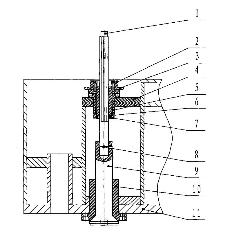
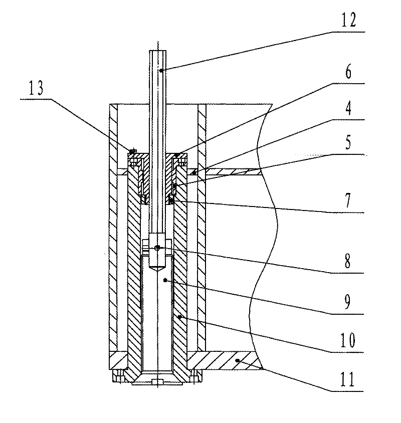
[0014] exist figure 1 Among them, the upper fixing seat 5 and the lower fixing seat 10 are respectively positioned and installed on the upper side plane 4 of the upper template and the lower side plane 11 of the upper template, the sliding sleeve 6 and the inner hole of the upper fixing seat 5 are slidingly fitted, and the locking nut 7 restricts the sliding sleeve 6 Axial movement, the spline shaft 1 passes through the sliding sleeve 6 and is fixed by the positioning pin 8 and the iron stop 9, the iron stop 9 and the lower fixing seat 10 are threadedly connected, and the rotating spline shaft 1 can drive the iron stop 9 in the lower fixing seat 10 Rotate to realize the axial adjustment of the stopper 9. The sprocket 3 is fixed by the sprocket fixing block 2 and the sliding sleeve 6, which can realize the synchronous adjustment of multiple stoppers. The...


PUM


Abstract

The invention discloses a stop iron mechanism of a cutting machine. The stop iron mechanism comprises an upper fixing base, a lower fixing base, a sliding bush, stop iron and a hexagonal shaft, wherein the flange end of the lower fixing base is fixed on the lower side plane of an upper template of the cutting machine; the other end of the lower fixing base passes through the upper template of the cutting machine and extends to the upper side plane of the upper template of the cutting machine; the upper fixing base is fixed on the lower fixing base; the sliding bush is in sliding fit in the upper fixing base, but is fixed axially; the hexagonal shaft is fixed by passing through the sliding bush and the stop iron; the stop iron is in threaded connection with the lower fixing base; by rotating the hexagonal shaft, the stop iron can be driven to move axially in the lower fixing base, so that the stop iron can be adjusted; and every part is positioned on the basis of the lower fixing base. The stop iron mechanism has a simplified structure, the processing and assembling accuracies are easy to ensure, and sticking phenomenon is avoided; and the stop iron is adjusted and locked separately, so that the requirements of practical work are met.

Description

technical field [0001] The invention relates to a cutting machine for processing sheet-shaped flexible materials in the light industry, in particular to an iron stop adjusting mechanism of a high-precision cutting machine. Background technique [0002] High-precision precision four-column cutting machines are generally equipped with an iron stop mechanism next to the four guide columns to ensure accurate positioning of the lower limit of cutting, so as to achieve some cutting operations with high requirements, such as half-cutting, film printing, etc., the adjustment mechanism Contains upper fixing seat, lower fixing seat, sliding sleeve, spline shaft, iron stopper, the upper fixing seat and the lower fixing seat are installed on the upper and lower planes of the upper template of the cutting machine respectively, and the outer circle of the sliding sleeve and the upper fixing seat slide fit , can rotate freely, but is axially fixed. The inner hole of the sliding sleeve is a...

Claims


Application Information

Patent Timeline
Patent Type & Authority Applications(China)
IPC IPC(8): B26D7/26
Inventor 朱春才
Owner YANCHENG ZHICHENG MASCH MFG CO LTD
Why Eureka
Try Eureka