Variable displacement oil pump

A displacement machine, a variable technology, applied in the direction of lubricating pumps, mechanical equipment, engine components, etc., can solve the problems of reducing pressure, not meeting energy saving and emission reduction, and difficult displacement, so as to reduce energy loss and reduce hydraulic power And mechanical power, efficiency improvement effect

Inactive Publication Date: 2012-02-29
SHANGHAI XINGFU MOTORCYCLE
View PDF6 Cites 22 Cited by
  • Summary
  • Abstract
  • Description
  • Claims
  • Application Information

AI Technical Summary

Problems solved by technology

The oil pump for automobile engine with the above structure still has a disadvantage in practical application: because the traditional oil pump does not have the function of variable displacement, the flow rate of the oil pump is relatively large when the engine is running at high speed, and the engine does not need Such a large flow rate leads to a relatively high pressure in the engine lubrication system, so a pressure limiting valve system is needed to release the excess oil through the pressure limiting valve to reduce the pressure. In this process, the excess oil causes the engine to run A lot of useless work, so the engine consumes a lot of power, which makes the engine consume a lot of fuel, which cannot meet the effect of energy saving and emission reduction
The above-mentioned structure has the following characteristics and defects: 1) The reduction of displacement is achieved by reducing the number of teeth in the oil-absorbing area, rather than directly in the oil outlet chamber, so it is difficult to control the excess displacement; 2) When the displacement continues to increase When it is large, it can only be realized by the overflow oil from the oil outlet chamber returning to the oil suction chamber. There is no dedicated return channel, and the engine still does a lot of useless work

Method used


Image

  • Variable displacement oil pump
  • Variable displacement oil pump
  • Variable displacement oil pump

Examples


Embodiment Construction

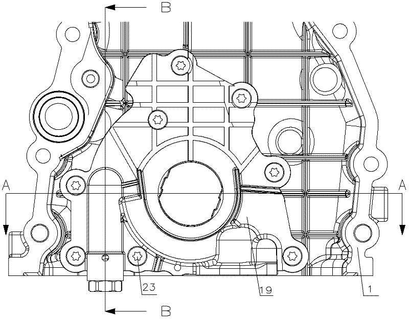
[0040] see figure 1 , the variable displacement oil pump for automobile engines involved in the present invention includes a pump body 1 and a pump cover 19 , and the pump body 1 and the pump cover 19 are connected by bolts 23 .

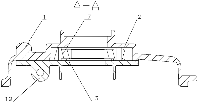
[0041] see Figure 8 (combined Figure 6 , Figure 7 ), which is a structural schematic diagram of the variable displacement oil pump for automobile engine involved in the present invention, and is also an initial state diagram. Including the pump body 1, the pump body 1 is provided with an inner chamber 10, the inner chamber 10 is provided with a stator 2, the stator 2 can rotate relative to the pump body 1 in the inner chamber 10, and the rotation center of the stator 2 is not at the stator 2 at the geometric center of . The stator 2 is provided with a rotor 7 connected to the engine crankshaft, the stator 2 and the rotor 7 are eccentrically arranged, and the rotor 7 is provided with a plurality of blades 5 on the circumference, and the ends of...


PUM


Abstract

The invention discloses a variable displacement oil pump for an automotive engine. The variable displacement oil pump comprises a pump body, wherein an inner cavity is formed in the pump body; a stator is arranged in the inner cavity; a rotor connected with an engine crankshaft is arranged in the stator; the stator and the rotor are eccentrically arranged; the rotor is provided with a plurality of blades at the periphery; the tail ends of the blades are contacted with the stator; the inner cavity between the rotor and the stator is divided into a plurality of volume cavities; the volume cavities comprise the maximum volume cavity and the minimum volume cavity; the stator is provided with a bump; the first side face of the bump is connected with an elastic element, and the second side face of the bump is connected with an oil return circuit control cavity; the oil return circuit control cavity is communicated with a main oil passage of the engine; and when the pressure in the oil return circuit control cavity is increased, the bump drives the rotor to rotate and squeezes the elastic element, and the maximum volume cavity is communicated with an oil outlet cavity of the engine. The displacement of the variable displacement oil pump is changed by changing the eccentricity of the stator and the rotor of the pump according to the change of the pressure of the main oil passage and the speed of the engine, unnecessary energy loss is reduced, the effects of saving energy and reducing emission are achieved, the hydraulic power and the mechanical power are reduced, and the efficiency of the engine is obviously improved.

Description

technical field [0001] The invention belongs to the technical field of automobile engine lubrication, and in particular relates to a vane-type variable-displacement oil pump for automobile engines. Background technique [0002] At present, the traditional oil pump used for automobile engines generally includes a pump cover and a pump body, and the pump cover and the pump body are connected by screws. The pump body is provided with an inner rotor, an outer rotor, a low-pressure oil chamber and a high-pressure oil chamber; the pump body There is an oil seal on the top, and a pressure limiting valve on the pump cover. The oil pump for automobile engine with the above structure still has a disadvantage in practical application: because the traditional oil pump does not have the function of variable displacement, the flow rate of the oil pump is relatively large when the engine is running at high speed, and the engine does not need Such a large flow rate leads to a relatively hi...

Claims


Application Information

Patent Timeline
Patent Type & Authority Applications(China)
IPC IPC(8): F16N13/20
Inventor 黄新良李金国白长安
Owner SHANGHAI XINGFU MOTORCYCLE
Why Eureka
Try Eureka