Supercharge Your Innovation With Domain-Expert AI Agents!

Electric junction box

A technology for electric junction boxes and shells, which is applied in the field of electric junction boxes, and can solve problems such as cracks, damages, and warping of bolt fixing parts of electric junction boxes, so as to prevent cracks and damages, achieve mutual reinforcement effects, and improve deformation The effect of intensity

Inactive Publication Date: 2015-06-24
SUMITOMO WIRING SYST LTD
View PDF5 Cites 0 Cited by
  • Summary
  • Abstract
  • Description
  • Claims
  • Application Information

AI Technical Summary

Problems solved by technology

[0004] However, in the case of making the plate thickness of the bolt fixing portion large, the bolt fixing portion protrudingly provided integrally with the case of the electrical junction box is susceptible to warpage due to thermal shrinkage after injection molding
As a result, it becomes difficult to secure the flatness of the bolt fixing portion, and it becomes difficult to completely tighten the attachment bolt, so that the required fixing force by the attachment bolt cannot often be obtained.
[0005] When the coupling bolt is tightened, warpage in the bolt fixing portion may cause unintended stress concentration in the bolt fixing portion and on the case side, possibly causing cracks or breakage in the electrical junction box

Method used


Image

  • Electric junction box
  • Electric junction box
  • Electric junction box

Examples


Embodiment Construction

[0022] Embodiments of the present invention will be described below with reference to the drawings.

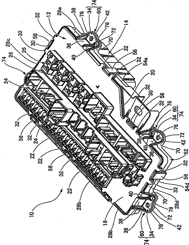
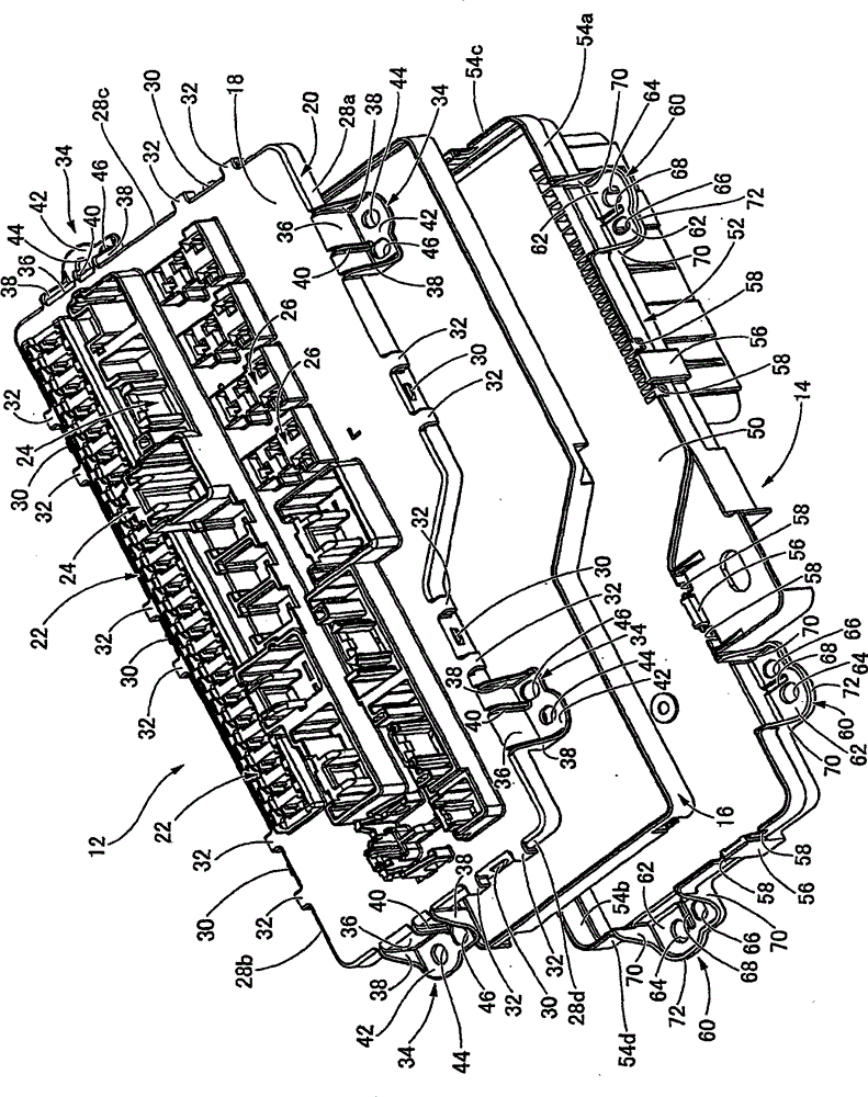
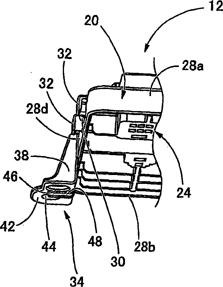
[0023] first reference figure 1 and figure 2 , figure 1 and figure 2 An electrical junction box 10 for an automobile according to an embodiment of the present invention is shown in a perspective view in an assembled state and a perspective view in an exploded state, respectively. from its figure 1 and figure 2 As clearly seen in , the electrical junction box 10 includes an upper case 12 as a first case and a lower case 14 as a second case, and these cases are combined with each other in an up-down direction, thereby constituting the electrical junction box 10 . In addition, inside such an electrical junction box 10 is formed a predetermined accommodation space in which the circuit body 16 is accommodated by assembling unillustrated bus bars, single core wires, and connection terminals on an insulating plate. And constitute the internal circuit. In the following descr...


PUM


Abstract

PROBLEM TO BE SOLVED: To provide an electric connection box including a bolt fixing portion capable of securing sufficient rigidity which withstands fastening torque of a mounting bolt while suppressing warpage. SOLUTION: A first fixture plate 42 and a second fixture plate 62 are respectively projected on peripheral walls 20 and 52 of a first case 12 and a second case 14. A first reinforcement rib 38 and a second reinforcement rib 70, which are respectively projected outward from the peripheral walls 20 and 52, are concatenated on both side edges of the fixture plates 42 and 62. Further, a peripheral rib 72 is formed on an outer periphery of the second fixture plate 62. The first fixture plate 42 and the first reinforcement rib 38 are respectively lapped with the second fixture plate 62 and the second reinforcement rib 70, and the first fixture plate 42 is fitted into the inner side of the peripheral rib 72 to form a bolt fixing portion 74 having an insertion hole 76 of a mounting bolt.

Description

technical field [0001] The present invention relates to an electrical junction box bolted to a support member of an automobile. Background technique [0002] Today, electrical junction boxes such as fuse boxes, relay boxes, or junction boxes have been fitted inside vehicles or in engine rooms of automobiles. Such electrical junction boxes are typically bolted to an automotive support member such as a body panel or instrument panel. For example, as shown in JP-A-2003-92816, a bolt fixing portion is protrudingly provided at a synthetic resin case of an electric junction box, and coupling bolts are screwed through bolt insertion holes provided in the bolt fixing portion. to the support member, thereby fixing the electrical junction box to the vehicle body side support portion. [0003] In the case where the electrical junction box is fixed to the supporting member, in order to prevent the electrical junction box from being displaced or separated from the supporting member due...

Claims


Application Information

Patent Timeline
Patent Type & Authority Patents(China)
IPC IPC(8): H02G3/08H05K5/02
Inventor 奥平裕介服部佑一
Owner SUMITOMO WIRING SYST LTD
Features
  • R&D
  • Intellectual Property
  • Life Sciences
  • Materials
  • Tech Scout
  • Unparalleled Data Quality
  • Higher Quality Content
  • 60% Fewer Hallucinations
Learn More