Fuel saving control device for working machine and fuel saving control method for working machine

A technology for working vehicles and working devices, which is applied to control devices, lifting devices, vehicle components, etc., and can solve problems such as poor energy recovery and regeneration efficiency, energy conversion loss, and hindrance to fuel-saving effects

Inactive Publication Date: 2014-07-30
KOMATSU LTD
View PDF5 Cites 2 Cited by
  • Summary
  • Abstract
  • Description
  • Claims
  • Application Information

AI Technical Summary

Problems solved by technology

[0005] However, in the device of the above-mentioned Patent Document 1, the kinetic energy of the vehicle is temporarily converted into electric energy, and the electric energy is derived from the conversion, so energy conversion loss occurs.
Specifically, the following losses occur: losses when kinetic energy from the vehicle is converted into electric energy, losses when the converted electric energy is stored in the power storage mechanism, losses when electric energy is derived from the power storage mechanism, and the derivation of the electric energy. The loss when the electrical energy is converted into kinetic energy
That is, the energy recovery and regeneration efficiency is poor, and as a result, there is a problem that it hinders the realization of the fuel-saving effect
In addition, there is a problem that the cost of the electric motor that converts the kinetic energy of the vehicle into electric energy and vice versa, the power storage device that accumulates electric energy, and the control device for controlling the above two components is very high

Method used


Image

  • Fuel saving control device for working machine and fuel saving control method for working machine
  • Fuel saving control device for working machine and fuel saving control method for working machine
  • Fuel saving control device for working machine and fuel saving control method for working machine

Examples


Embodiment approach 1

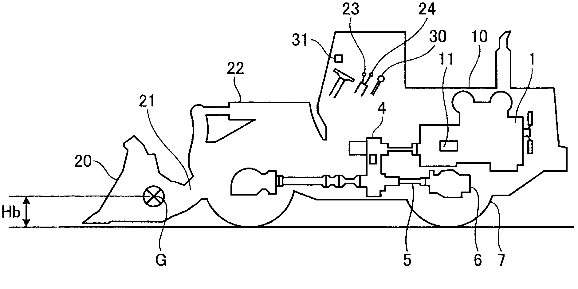
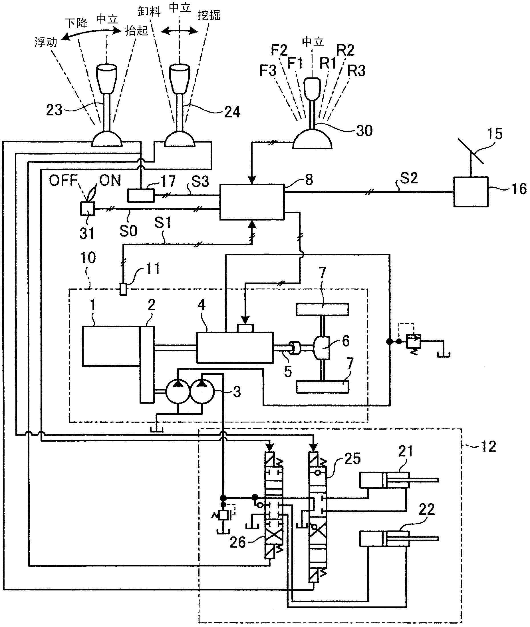
[0030] figure 1 It is a schematic diagram showing a schematic configuration of a wheel loader to which the fuel-saving control device for a work vehicle according to Embodiment 1 of the present invention is applied. figure 2 is included in the figure 1 It is a block diagram showing the structure of the fuel-saving control device of the work vehicle of the wheel loader shown. exist figure 1 and figure 2 In the wheel loader, an engine 1 is mounted on the rear of a vehicle body 10, and is connected to a travel transmission 4 and a fixed displacement hydraulic pump 3 via a PTO 2 that extracts the rotational force of the engine 1 to the outside.

[0031] The travel transmission 4 is a continuously variable transmission, and is realized by an HST (Hydro-Static Transmission) or a belt-type continuously variable transmission. The travel transmission 4 decelerates and speeds up the rotating shaft based on instructions from the controller 8 . The output side of the travel transmi...

Embodiment approach 2

[0044] Next, Embodiment 2 of the present invention will be described. In the first embodiment described above, the hydraulic pump 3 is a fixed-displacement hydraulic pump, but in this second embodiment, a variable-displacement hydraulic pump 33 is used as a hydraulic pump of the work implement.

[0045] That is, if Figure 5 As shown, a variable displacement hydraulic pump 33 is provided instead of the fixed displacement hydraulic pump 3 . The hydraulic pump 33 uses the controller 8 to control the inclination of the swash plate of the hydraulic pump 33 , thereby changing the capacity of the hydraulic pump 33 . Furthermore, when the accelerator pedal is released during travel and the arm is raised, the controller 8 performs control to increase the speed reduction ratio of the travel transmission 4 compared to the normal case as in the first embodiment, and Control is performed to increase the capacity of the hydraulic pump 33 . In this case, it is preferable that the capacit...

Embodiment approach 3

[0052] Next, Embodiment 3 of the present invention will be described. In the first and second embodiments described above, the travel transmission 4 is a continuously variable transmission, but in this third embodiment, the travel transmission 4 is a stepped transmission. Other structures are the same as those in Embodiment 1.

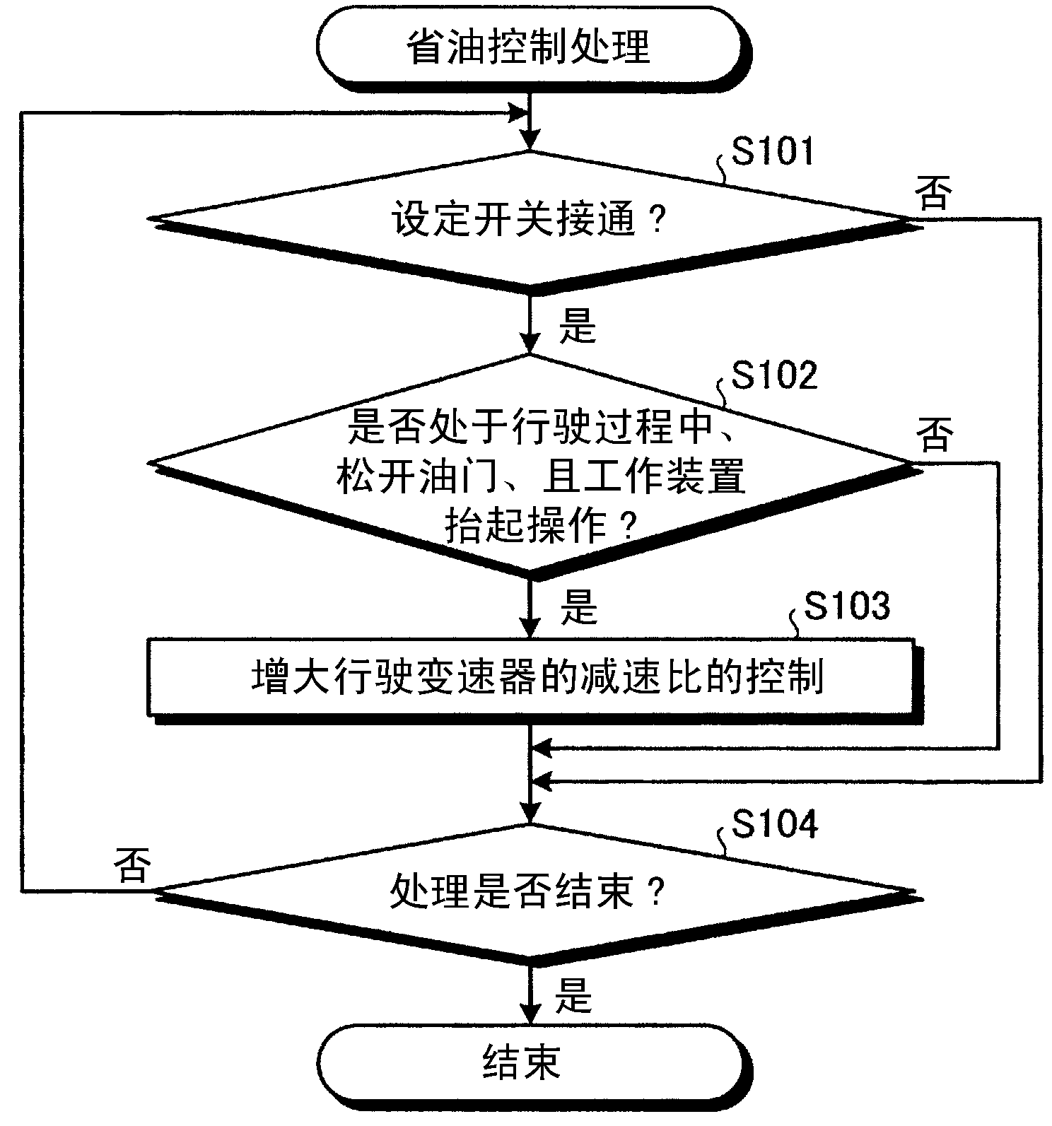
[0053] Here, refer to Figure 8 The timing chart shown here describes the operation of each part when the fuel-saving control process according to Embodiment 3 of the present invention is performed. It should be noted, Figure 8 The dotted line in the circle represents the fuel-saving control processing of the stepped transmission according to the third embodiment, and the solid line represents the fuel-saving control processing of the continuously variable transmission according to the first embodiment. exist Figure 8 , firstly, release the accelerator before time t1 (refer to Figure 8 (a)), the vehicle speed V(S1) is above the fixed value Vth ...


PUM


Abstract

An object of the present invention is to provide a fuel-saving control device for a work vehicle and a fuel-saving control method for a work vehicle, which can improve energy recovery / regeneration efficiency and further promote fuel saving. The fuel-saving control device of the work vehicle has: a vehicle speed detector (11), which detects whether it is in the process of driving; an accelerator operation detector (16), which detects whether it is in a state where the accelerator operation part is not operated; 23), which detects whether there is an instruction to lift the arm for loading, unloading and transporting operations; the controller (8), when the vehicle speed detector (11) detects that it is in the process of driving, and the accelerator operation detector (16) detects that it is in the The controller (8) performs control to increase the speed reduction ratio of the travel transmission (4) when the accelerator operating member is not operated and the arm operating lever (23) detects an arm raising operation instruction.

Description

technical field [0001] The present invention relates to a fuel-saving control device for a work vehicle and a fuel-saving control method for a work vehicle, which can realize fuel-saving of work vehicles such as wheel loaders and forklifts that perform loading, unloading, and transportation operations. Background technique [0002] Conventionally, V-shaped loading has been described as an example of a typical operation in which a wheel loader is often used. V-shaped loading refers to an operation in which loading is repeatedly carried out so as to draw a V-shaped trajectory with respect to a pile of sand or gravel and a dump truck. In this case, since the wheel loader repeats forward / backward and repeated excavation / dumping, there is not only the problem of increased fuel consumption during acceleration, but also the problem of brake heating due to increased brake load during deceleration ( overheating), and the maintenance costs are also high due to brake wear. [0003] T...

Claims


Application Information

Patent Timeline
Patent Type & Authority Patents(China)
IPC IPC(8): B66F9/22E02F9/22
CPCE02F9/2282B60W2540/16E02F9/2253E02F9/2217B60W2540/10B60W2520/10B66F9/20B60Y2200/415E02F9/2292E02F9/2296
Inventor 金山登小松健浩
Owner KOMATSU LTD
Why Eureka
Try Eureka