Air-conditioning apparatus
A technology of air conditioning and heat medium, applied in space heating and ventilation details, climate sustainability, energy-saving heating/cooling, etc., can solve the problems of heat medium leakage detection, no consideration, etc.
- Summary
- Abstract
- Description
- Claims
- Application Information
AI Technical Summary
Problems solved by technology
Method used
Image
Examples
Embodiment approach 1
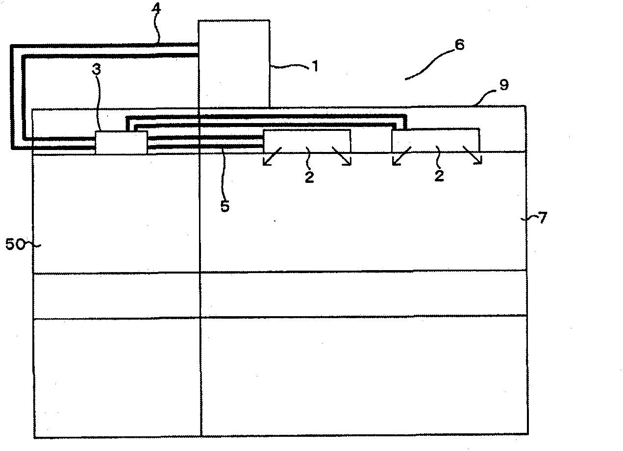
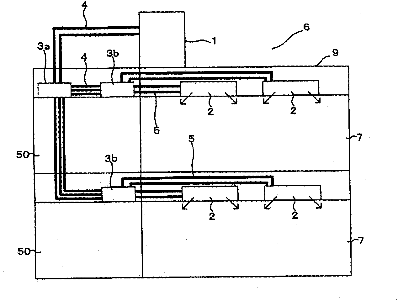
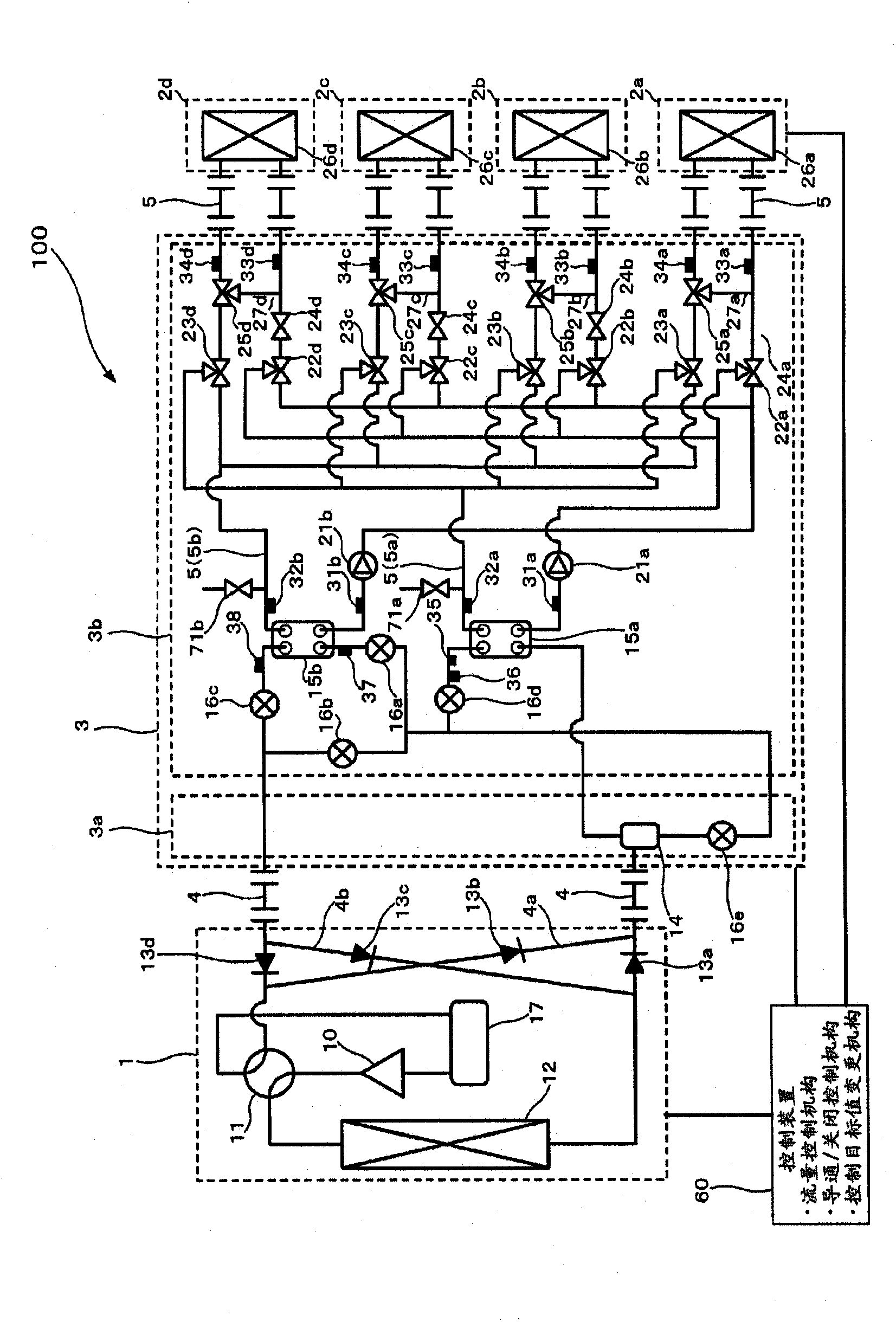
[0030] figure 1 and figure 2 It is an overall configuration diagram showing an example of the installation state of the air-conditioning apparatus according to Embodiment 1 of the present invention. based on figure 1 and figure 2 The structure of the air conditioning device will be described. This air conditioner performs a cooling operation or a heating operation using a refrigeration cycle (a refrigeration cycle and a heat medium circulation circuit) in which a refrigerant (a heat source side refrigerant and a heat medium (water, antifreeze, etc.)) circulates. Additionally, when including figure 1 In the following drawings, the relationship between the sizes of the components may be different from the actual situation.
[0031] Such as figure 1 As shown, the air conditioner has: one heat source device 1 as a heat source unit; multiple indoor units 2; and a relay unit 3 interposed between the heat source device 1 and the indoor units 2 . The relay unit 3 is used to exc...
Embodiment approach 2
[0148] In Embodiment 1, the leakage of the heat medium from the heating medium circulation circuit and the leakage of the heat medium from the cooling heat medium circulation circuit are detected in one process ( Figure 8 ). Not limited to this, the leakage of the heat medium from the heating medium circulation circuit and the leakage of the heat medium from the cooling heat medium circulation circuit may be detected through other steps. In addition, in this Embodiment 2, about the item which is not demonstrated especially, it is the same as Embodiment 1, and about the same function and structure, it demonstrates using the same code|symbol.
[0149] Figure 9 and Figure 10 It is a flowchart showing an example of a heat medium leakage detection method according to Embodiment 2 of the present invention. Figure 9 It is a flowchart showing the detection method of the heat leak from the heat source circulation circuit for heating. Figure 10 It is a flowchart showing a detec...
Embodiment approach 3
[0164] In Embodiment 1 and Embodiment 2, the leakage of the heat medium from the heat medium circuit is detected based on the temperature of the heat medium circulating in the heat medium circuit. Not limited thereto, the leakage of the heat medium from the heat medium circulation circuit may be detected based on the current value of the pump 21 . In this Embodiment 3, items not particularly described are the same as Embodiment 1 or Embodiment 2, and the same functions and configurations are described using the same reference numerals.
[0165] Figure 11 It is a schematic circuit diagram showing the structure of the air-conditioning apparatus in Embodiment 3 of this invention. Such as Figure 11 As shown, the first pump 21a installed on the heating medium circulation circuit is provided with a current detection unit that detects the current flowing in the first pump 21a (more specifically, the motor of the first pump 21a). 75a. In addition, the second pump 21b provided on...
PUM
 Abstract
Description
Claims
Application Information
 - R&D
- Intellectual Property
- Life Sciences
- Materials
- Tech Scout
- Unparalleled Data Quality
- Higher Quality Content
- 60% Fewer Hallucinations
Browse by: Latest US Patents, China's latest patents, Technical Efficacy Thesaurus, Application Domain, Technology Topic, Popular Technical Reports.
© 2025 PatSnap. All rights reserved.Legal|Privacy policy|Modern Slavery Act Transparency Statement|Sitemap|About US| Contact US: help@patsnap.com


