Cutter radius compensation method for five-axis numerical control side milling machining

A technology of tool radius and compensation method, used in metal processing, manufacturing tools, metal processing equipment, etc., can solve problems such as increased processing costs, difficulty in NC program maintenance, and reduced NC program applicability

Active Publication Date: 2012-03-14
SHENYANG CALCULATION TECH INST CHINESE ACAD OF SCI
View PDF2 Cites 16 Cited by
  • Summary
  • Abstract
  • Description
  • Claims
  • Application Information

AI Technical Summary

Problems solved by technology

However, the above two methods have the disadvantages of increasing processing costs and difficulty in maintainin

Method used


Image

  • Cutter radius compensation method for five-axis numerical control side milling machining
  • Cutter radius compensation method for five-axis numerical control side milling machining
  • Cutter radius compensation method for five-axis numerical control side milling machining

Examples


Example Embodiment

[0043] The method of the present invention will be further described in detail below in conjunction with the accompanying drawings.

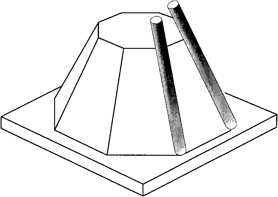
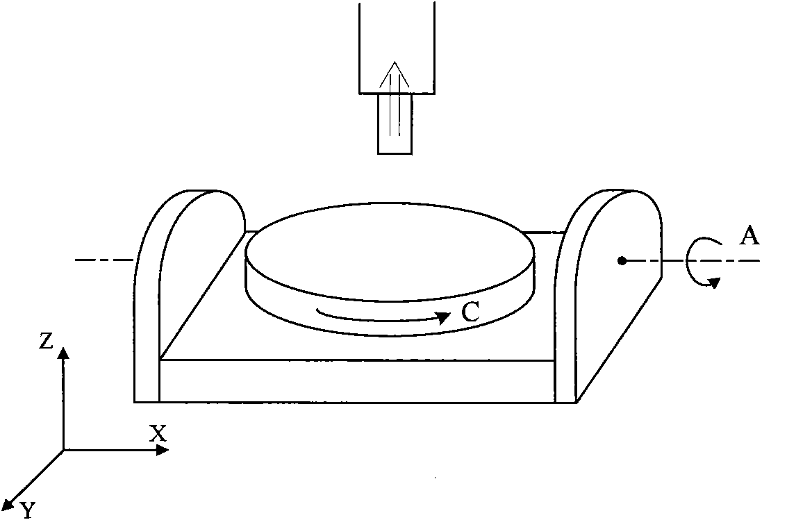
[0044] Such as figure 1 As shown, the method of the present invention is applied to the five-axis side milling process, the frustum in the figure is the workpiece to be processed, and the tool adopts the line cutting mode of side edge milling. Such as figure 2 Shown is a schematic diagram of the structure of an AC double turntable five-axis machine tool used in the method of the present invention.

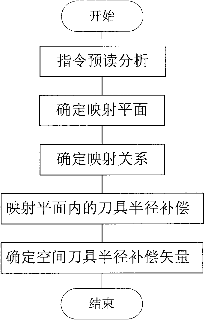
[0045] Such as image 3 As shown, the tool radius compensation method for five-axis numerical control side milling of the present invention includes the following steps:

[0046] Command pre-reading analysis: Determine the tool offset direction and tool radius in the programming coordinate system, and determine the coordinate of the tool center point and the tool axis vector of each point on the processing path;

[0047] Determine the mapping plane: Determi...


PUM


Abstract

The invention relates to a cutter radius compensation method for five-axis numerical control side milling machining. The cutter radius compensation method comprises the following steps of: 1) pre-reading and analyzing an instruction: confirming a cutter offset direction and a cutter radius and confirming a cutter central point coordinate and a cutter axial vector of each point on a machining path; 2) confirming a mapping plane: confirming a corresponding mapping plane of each point according to the cutter central point coordinate and the cutter axial vector of each point on the machining path; 3) confirming a mapping relation: confirming a space coordinate conversion relation between a programming coordinate system and a mapping plane coordinate system; 4) compensating a radius of a cutter in the mapping plane: converting the cutter central point coordinate of each point under the programming coordinate system into a coordinate in the mapping plane coordinate system and confirming a cutter compensation vector corresponding to each point; and 5) confirming a space cutter radius compensation vector: confirming a compensated cutter central point coordinate of the mapping plane coordinate system and confirming the cutter central point coordinate corresponding to each point after being subjected to space cutter compensation. The cutter radius compensation method provided by the invention is used for solving the problem of an invalid cutter radius compensation function in five-axis machining and promoting the applicability and operability of a five-axis NC (Numerical Control) program.

Description

technical field [0001] The invention relates to a numerical control device for controlling a five-axis numerical control machine tool in a numerical control system, in particular to a tool radius compensation method for five-axis numerical control side milling. Background technique [0002] Five-axis CNC machining is an advanced manufacturing technology developed to overcome the shortcomings of three-axis machining. By adding two rotation axes, the flexibility of machining is greatly enhanced. It has obvious advantages and important practical significance in industries such as , ships and molds. The five-axis CNC machine tool moves the tool in three linear axes relative to the workpiece, and at the same time rotates around the two axes so that the tool feeds the workpiece at different angles, and can provide a line cutting mode for side edge milling. Compared with the end milling mode of point cutting, it can not only greatly improve the processing efficiency, but also impr...

Claims


Application Information

Patent Timeline
IPC IPC(8): B23Q15/16
Inventor 林浒于东郑飂默张富彦张晓辉杨富枝王峰
Owner SHENYANG CALCULATION TECH INST CHINESE ACAD OF SCI
Why Eureka
Try Eureka