Method for detecting business security of station in-out cable of transmission network station

A detection method and security technology, applied in the field of transmission network and communication resource management, can solve the problems of lack of comprehensive management, misanalysis, error-prone, etc., and achieve the effect of saving labor cost, high efficiency and high accuracy

Active Publication Date: 2012-03-14
北京直真科技股份有限公司
View PDF3 Cites 16 Cited by
  • Summary
  • Abstract
  • Description
  • Claims
  • Application Information

AI Technical Summary

Problems solved by technology

If the incoming and outgoing optical fibers AB and AG of office A share the same cable and bearer point, once the optical cable is interrupted, office A will become a network island, and the self-healing protection capability of the equipment will not take effect
[0004] From the point of view of the current management and maintenance of the transmission network, in order to realize the analysis of the reliability of the incoming and outgoing optical cables and business protection of the automatic office station, the existing problems and defects are as follows: ①The structure of the transmission network is complex, and for the relatively important , The number of lines between the core office and adjacent office stations is even greater; at the same time, it is also necessary to consider the

Method used


Image

  • Method for detecting business security of station in-out cable of transmission network station
  • Method for detecting business security of station in-out cable of transmission network station
  • Method for detecting business security of station in-out cable of transmission network station

Examples


Embodiment Construction

[0029] Below with the accompanying drawings ( Figure 2-Figure 4 ) to illustrate the present invention.

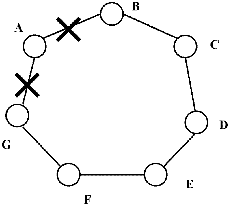
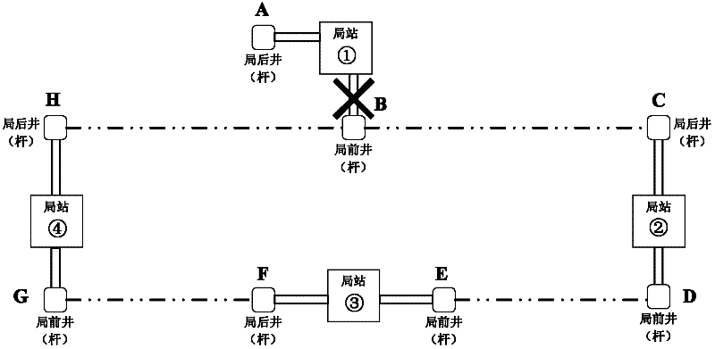
[0030] figure 2 It is a schematic diagram of the physical connection network model between stations. The core idea of ​​the present invention is: connect the static fiber core, optical cable, and physical bearing facilities of the optical cable (man wells, pipelines, poles, overhead, etc.) The associated concatenation of the in-office and out-of-office common cables and common bearing points that may cause the total blockage of a large number of services in the office is found out by combining the concatenation results with the transmission system to find out the safety hazards of optical cable business protection security.

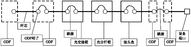
[0031] Explanation of hidden danger definition: Hidden danger of co-cable of incoming and outgoing network optical fibers: the physical cores carried by the logical networking topology of the incoming and outgoing office are in the same optical cab...


PUM


Abstract

The invention relates to a method for detecting business security of a station in-out cable of a transmission network station, which can be used for analyzing the reliability of the station in-out cable and a business protection system according to a bearing relevance relation among a cable source, a transmission system and transmission network element equipment. The method comprises the following steps of: carrying out whole-course relevance serial connection on a fiber core with a static wire resource, an optical cable and a physical bearing facility of the optical cable which are arranged outside a station, and an optical distribution frame(ODF), a terminal, transmission equipment and a transmission equipment port which are arranged inside the station; and carrying out combined detection on a serial connection result and the transmission system to find out a cable potential safety hazard at a common bearing point of an in-out station common cable which can cause that in-station batch services are blocked. The combined detection comprises the following steps of: step 1, serially connecting fiber cores to form end-to-end optical fiber data; step 2, completing a relevance between the transmission system and physical optical fibers by means of relating a logic with a physical source; and step 3, analyzing the business security of the station in-out cable and then judging whether the potential safety hazard at the common bearing point of the common cable exists.

Description

technical field [0001] The invention relates to a transmission network and communication resource management technology, and relates to a method for detecting the security of the optical cable service protection of a transmission network station in and out of an office. By adopting the detection method, the reliability of inbound and outbound optical cables and service protection of the office station can be analyzed through the associated bearer relationship between the optical cable resources and the transmission system and transmission network element equipment. Background technique [0002] Network quality has always been the focus of operators' greatest concern. Network operation assurance has shifted from backward detection of faults and timely handling of faults to forward detection of network hidden dangers to avoid faults. The basis of the transmission network is the optical cable resource, and all services are carried on the optical cable. Because the communicatio...

Claims


Application Information

Patent Timeline
IPC IPC(8): H04B10/08H04B10/07
Inventor 袁隽黄志涛左世春
Owner 北京直真科技股份有限公司
Why Eureka
Try Eureka