Degassing technique for liquid sulfur

A liquid sulfur degassing and process technology, applied in the field of degassing process, can solve the problems of clogging the bubbler, easy partial condensation of the bubbler, unstable degassing effect, etc. low investment

Inactive Publication Date: 2012-03-21
CHINA PETROLEUM & CHEM CORP +1
View PDF2 Cites 47 Cited by
  • Summary
  • Abstract
  • Description
  • Claims
  • Application Information

AI Technical Summary

Problems solved by technology

[0005] The present invention provides a liquid sulfur degassing process aiming at the technical problems of easy pa

Method used


Image

  • Degassing technique for liquid sulfur
  • Degassing technique for liquid sulfur
  • Degassing technique for liquid sulfur

Examples


Embodiment Construction

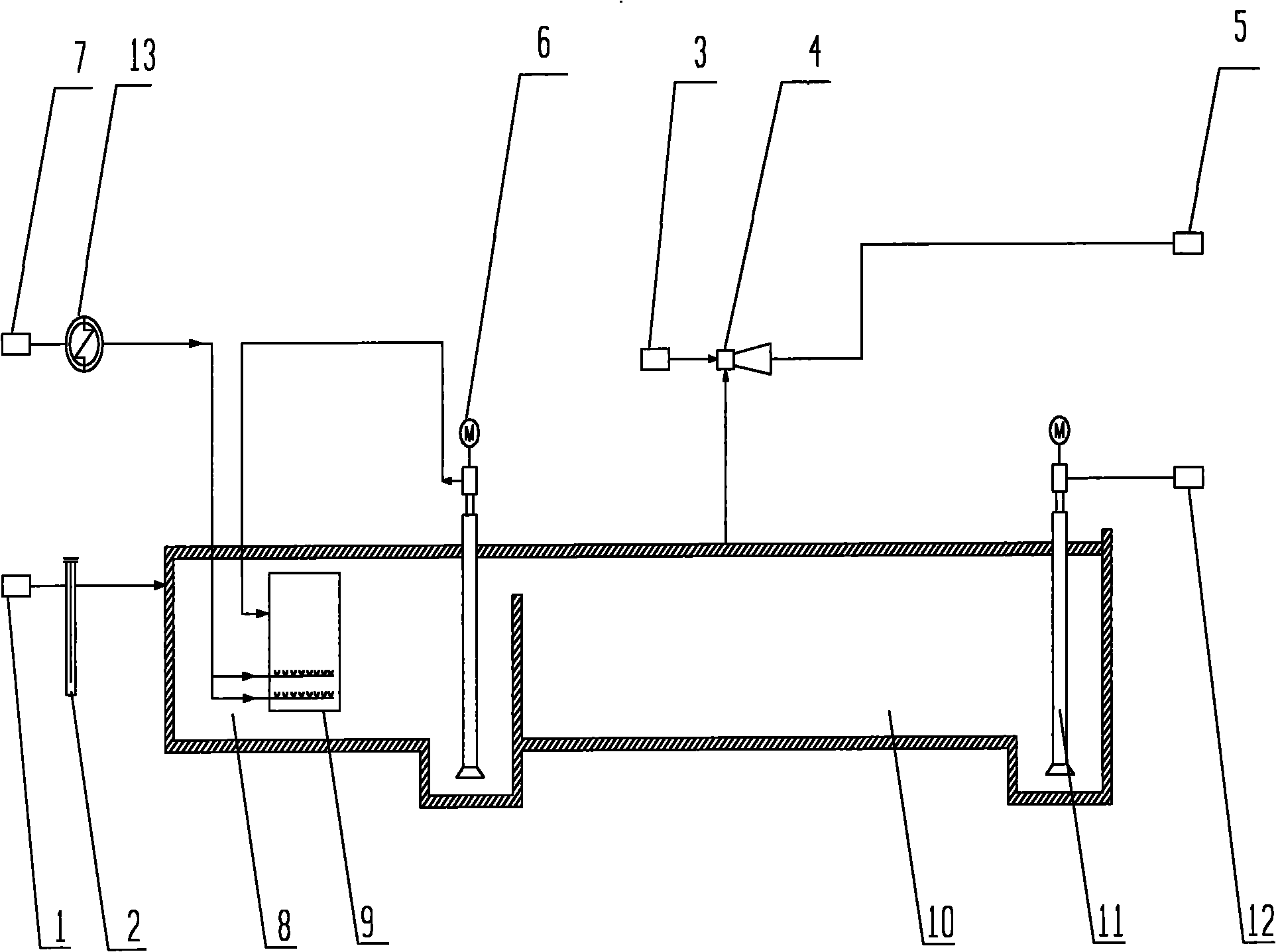
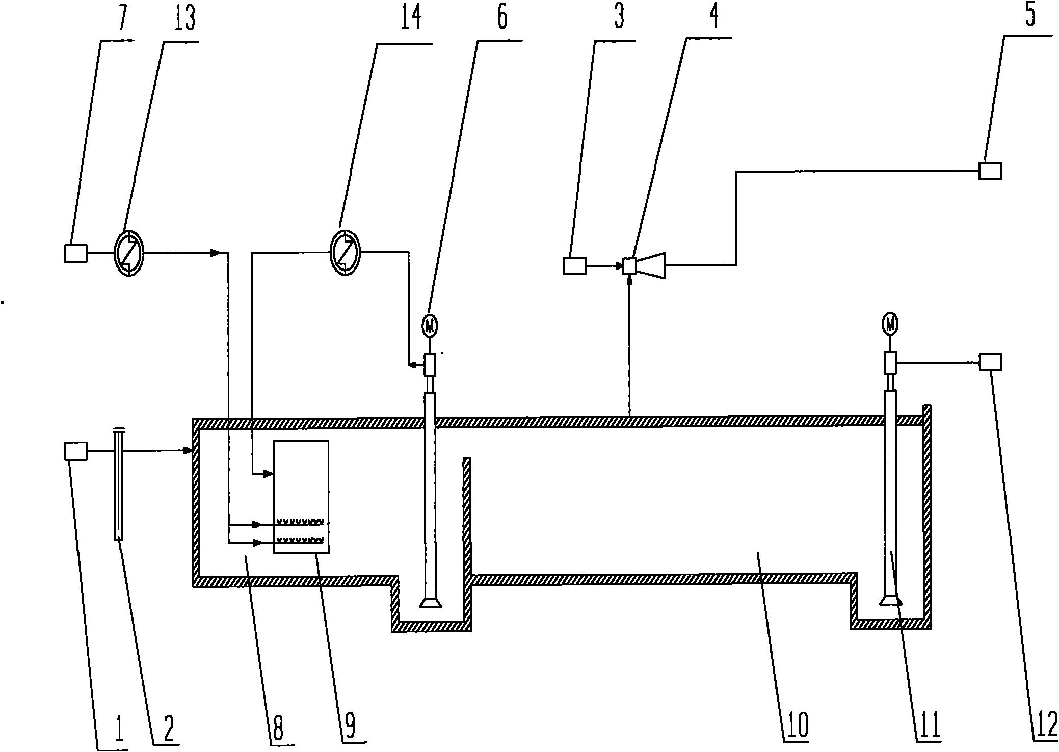
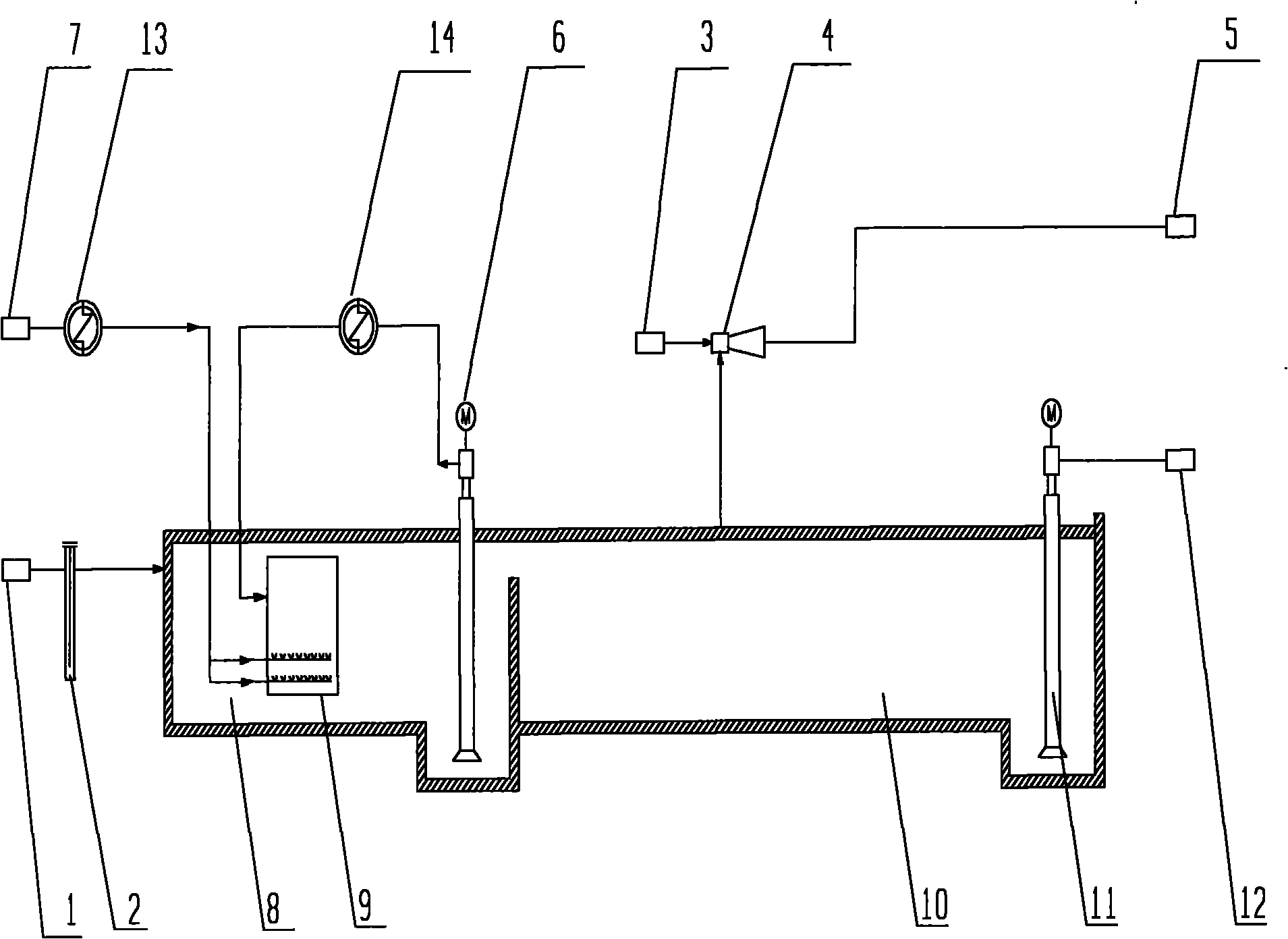
[0019] Combine below figure 1 The liquid sulfur degassing process of the present invention will be described in detail.

[0020] First, the liquid sulfur from the liquid sulfur inlet 1 enters the degassing section 8 through the sulfur seal 2, and the liquid sulfur in the degassing section 8 enters the upper part of the stripping degassing column 9 arranged in the degassing section 8 through the liquid sulfur degassing pump 6 .

[0021] The air enters the bubbling device at the bottom of the stripping and degassing column 9 after being heated to 130-140° C. from the air inlet 7 by the air preheater 13 . In the stripping and degassing column 9, the air lifts the liquid sulfur, and the liquid sulfur circulates inside and outside the stripping and degassing column 9, and the residual H 2 S x continue to convert to H 2 S, most of H 2 S is further oxidized to elemental S and H 2 O, H extracted from gas 2 S is pumped out through the steam evacuator 4 and sent to the tail gas i...


PUM


Abstract

The invention provides a degassing technique for liquid sulfur. The degassing technique can be used for solving the technical problems of the prior art that local condensation easily occurs in a bubbler, the bubbler is easily blocked and a degassing effect is unstable. The degassing technique comprises the following steps: A) entering into a degassing section after sealing the liquid sulfur, utilizing a liquid sulfur degassing pump to pressurize and send the liquid sulfur into a gas-stripping degassing column arranged in the degassing section, and circulating the liquid sulfur inside and outside the gas-stripping degassing column; B) heating compressed air and then introducing the compressed air into a bubbling device on the lower part of the gas-stripping degassing column, contacting the compressed air with the liquid sulfur in the gas-stripping degassing column, removing H2S dissolved in the liquid sulfur and burning the removed H2S after sending the removed H2S to a tail gas incinerator or an acid gas combustion furnace; and C) after overflowing the degassed liquid sulfur from the degassing section to a storage section, sending the liquid sulfur by a liquid sulfur end product pump. The degassing technique can be used for reducing the content of H2S in the liquid sulfur, preventing the bubbling device from being blocked, promoting the liquid sulfur degassing effect and achieving the content of the H2S in the liquid sulfur being less than 10ppm.

Description

technical field [0001] The invention relates to a degassing process in the oil and gas processing industry, in particular to a liquid sulfur degassing process, which can be used for the removal of hydrogen sulfide in liquid sulfur produced by sulfur recovery devices in refineries, oil and gas fields, etc. . Background technique [0002] In liquid sulfur produced by the CLAUS method, H 2 The S content is generally 300-400ppm. If it leaves the factory in the form of liquid sulfur, the H 2 S is easy to cause agglomeration, when reaching H 2 The explosion limit of S, the container itself has FeS which is easy to catch fire, or due to the accumulation of static electricity, it has the conditions for explosion; 2 S will escape and pollute the environment, the unescaped H 2 S remaining in solid sulfur will cause secondary pollution during the user's use. Therefore, no matter whether it is delivered in the form of solid sulfur or liquid sulfur, the H in liquid sulfur must be rem...

Claims


Application Information

Patent Timeline
IPC IPC(8): C01B17/02
Inventor 郭宏昶汤红年王刻文
Owner CHINA PETROLEUM & CHEM CORP
Why Eureka
Try Eureka