High-energy laser semi-integrating-sphere array attenuator

A semi-integrating sphere, high-energy laser technology, applied in the field of array attenuators, can solve the problems of large difference in the absorption coefficient of incident laser, limited application range, difficult parameter measurement, etc., to ensure consistency, ensure installation accuracy, and improve surface reflection. rate effect

Active Publication Date: 2012-03-21
NORTHWEST INST OF NUCLEAR TECH
View PDF3 Cites 18 Cited by
  • Summary
  • Abstract
  • Description
  • Claims
  • Application Information

AI Technical Summary

Problems solved by technology

The problem with this kind of attenuator is that it is difficult to measure the parameters when the strong laser is obliquely incident. When the laser enters the laser incident hole at a certain angle, the hole wall of the graphite material has a high absorption of the laser light, and it correspon...

Method used


Image

  • High-energy laser semi-integrating-sphere array attenuator
  • High-energy laser semi-integrating-sphere array attenuator
  • High-energy laser semi-integrating-sphere array attenuator

Examples


Embodiment Construction

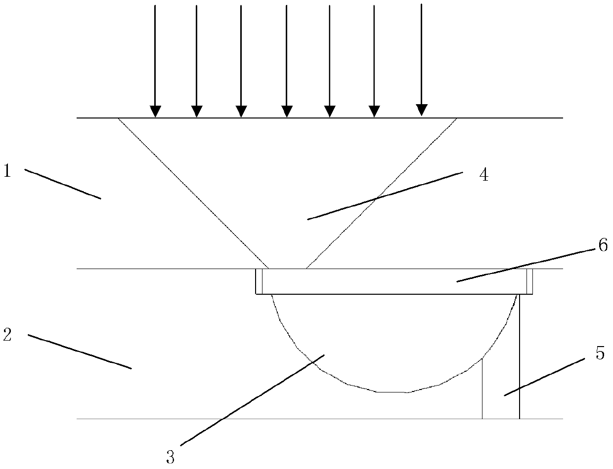
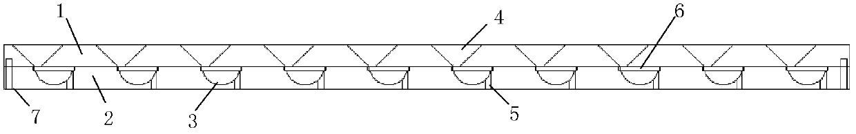
[0021] Such as figure 1 As shown, a large-angle sampling cone 4 is machined on the front panel 1, a hemispherical cavity 3 and a laser exit hole 5 are machined on the rear panel 2, and the two panels are superimposed to make the corresponding large-angle sampling cone 4 and the hemispherical cavity 3 are spliced ​​together to form a semi-integrating sphere inner cavity, and the large-angle sampling cone 4 and the laser exit hole 5 are located on both sides of the hemispherical cavity 3 respectively. Laser edge figure 1 In the direction of the middle arrow, the sampling cone 4 is coupled into the hemispherical cavity 3 from a large angle. After multiple absorption and reflection in the cavity, only a small part of the light is emitted from the laser exit hole 5 to achieve the attenuation of the strong laser power density . Due to the adoption of the large-angle sampling cone 4 structure, the attenuator can satisfy the oblique incidence of the laser within a certain angle range. ...


PUM


Abstract

The invention provides a high-energy laser semi-integrating-sphere array attenuator, which comprises a front panel arranged along a laser incident direction, a back panel and a plurality of attenuation units, wherein the attenuation units comprise wide-angle sampling taper holes arranged on the front panel, semi-sphere cavities arranged on the back panel, and laser emergent holes which are arranged on the edges of the semi-sphere cavities and are vertical to the back panel; the positions of the wide-angle sampling taper holes are corresponding to the positions of the semi-sphere cavities one to one; and the wide-angle sampling taper holes and the laser emergent holes are respectively arranged on the two sides of the semi-integrating-sphere cavities. In the attenuator provided by the invention, laser is coupled into the semi-sphere cavities via the wide-angle sampling taper holes, is absorbed and diffuse-reflected by the semi-sphere cavities, and then is ejected from the laser emergentholes, large amplitude attenuation of laser power density is realized, and the requirement of attenuation sampling during oblique incidence of the laser can be satisfied.

Description

Technical field [0001] The invention relates to an array attenuator for high-energy lasers, in particular to a semi-integrating sphere array attenuator for high-energy lasers. Background technique [0002] In the measurement of high-energy laser parameters, the photodetector array sampling method is often used to obtain the spatial-temporal distribution information of the laser spot power density. Because the laser power density at the test location is generally high, it is difficult to directly use the photodetector array to measure, so in actual testing, the measured laser power density needs to be reasonably attenuated to meet the range of the photodetector range. The ideal optical attenuation method should be independent of the incident laser wavelength, incident angle, polarization state and other parameters, and only attenuate the incident laser amplitude accordingly, and the attenuation is linear within a certain range. [0003] At present, the commonly used optical attenu...

Claims


Application Information

Patent Timeline
IPC IPC(8): G01J1/04
Inventor 杨鹏翎冯国斌吴勇王振宝武俊杰张检民叶锡生
Owner NORTHWEST INST OF NUCLEAR TECH
Why Eureka
Try Eureka