A Cone Cavity High Energy Laser Total Absorption Energy Meter

A technology of high-energy laser and energy meter, which is applied in the direction of using electric radiation detectors for photometry, etc., can solve problems such as the impact of high-energy laser measurement accuracy, achieve the effects of improving test capabilities, reducing escaped energy, and improving measurement accuracy

Active Publication Date: 2015-12-02
INST OF APPLIED ELECTRONICS CHINA ACAD OF ENG PHYSICS
View PDF6 Cites 0 Cited by
  • Summary
  • Abstract
  • Description
  • Claims
  • Application Information

AI Technical Summary

Problems solved by technology

If the influence of these factors is not controlled and compensated, it will have a serious impact on the accuracy of high-energy laser energy measurement

Method used


Image

  • A Cone Cavity High Energy Laser Total Absorption Energy Meter
  • A Cone Cavity High Energy Laser Total Absorption Energy Meter
  • A Cone Cavity High Energy Laser Total Absorption Energy Meter

Examples


Embodiment 1

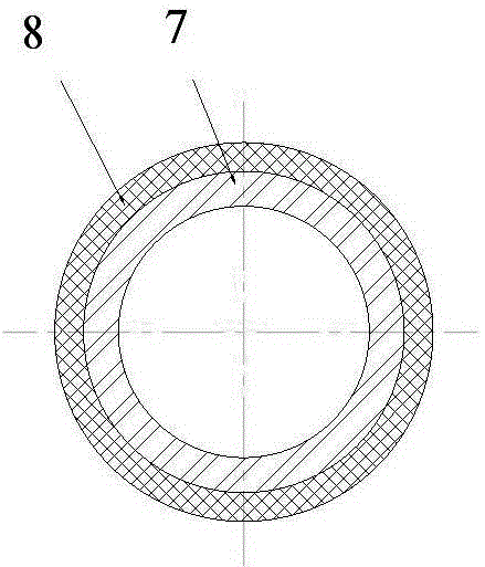
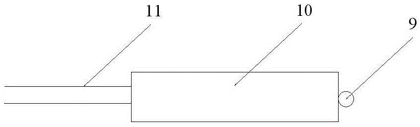
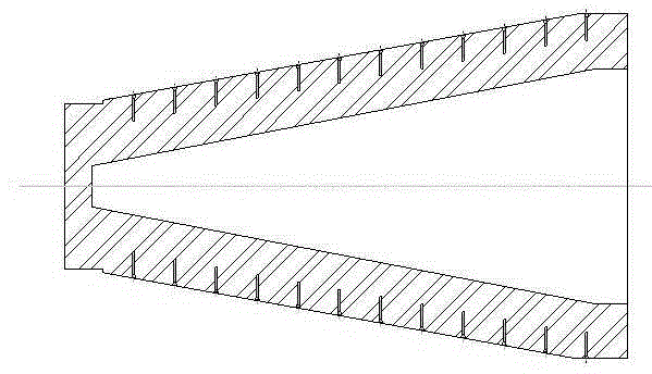
[0024] figure 1 It is the structural representation of the cone cavity type high-energy laser total absorption energy meter of the present invention, figure 2 It is a structural schematic diagram of the heat insulator in the present invention, image 3 It is a schematic structural diagram of a thermocouple sensor in the present invention, and Fig. 4 is a schematic diagram of the arrangement of sink holes on an absorber in the present invention, wherein Fig. 4(a) is a sectional view, Fig. 4(b) is a side view, and Fig. 5 It is a schematic diagram of the V-groove structure of the absorber in the present invention, Fig. 5(a) is a side view, and Fig. 5(b) is a cross-sectional view.

[0025] exist figure 1 ~Among Fig. 5, the conical cavity type high-energy laser total absorption energy meter of the present invention comprises absorber 1, thermocouple sensor 3, absorber support, cylindrical heat insulator 2, data acquisition system 6, shell 5; Wherein , The absorber support inclu...

Embodiment 2

[0037] The structure of this embodiment is the same as that of Embodiment 1, except that in this embodiment, the number of V-shaped grooves is 100, and the included angle θ of the V-shaped grooves is 60°. The counterbores provided on the absorber 1 are arranged equidistantly along the direction of the generatrix of the cone and perpendicular to the direction of the generatrix, and the distance between any two counterbores along the direction of the generatrix of the cone is equal to 6% of the length of the generatrix of the cone of the absorber . The reflecting plate is made of brass material, and the surface of the brass material is gold-plated.

[0038] Fifteen sets of thermocouple sensors are arranged equidistantly in the direction of the generatrix of the cone of the absorber. The diameter of the armored sleeve of the thermocouple sensor is 0.5mm smaller than the diameter of the sink hole on the absorber, and the length of the armored sleeve of the thermocouple sensor is ...


PUM


Abstract

The invention provides a conical cavity type high-energy laser total-absorption energy meter. The energy meter comprises an absorber, a thermocouple sensor, an absorber support, a barrel-shaped insulator, a data acquiring system and a shell, wherein the absorber is made of a high-purity graphite material and has a cone structure; a conical hollow cavity is formed in the absorber; the absorber support is fixedly connected with the shell in a threaded manner; the middle and the bottom of a cone of the absorber are arranged on the support; the insulator is arranged in the shell; the thermocouple sensor is adhered to counter bores in the surface of the absorber; the distance between the bottom of each counter bore in the absorber and the outer surface of the absorber is 40% of the thickness of the wall of the absorber; the counter bores are equidistantly formed along the cone busbar direction and the direction perpendicular to a busbar; and the distance between two optional counter bores along the cone busbar direction is smaller than the length of the cone busbar of the absorber by 10%. By using the conical cavity type high-energy laser total-absorption energy meter, the high-energy laser energy measuring precision can be obviously improved; and the testing capability of the high-energy laser total-absorption energy meter is improved.

Description

technical field [0001] The invention belongs to the field of high-energy laser energy measurement, in particular to a cone-cavity high-energy laser total absorption energy meter, which is suitable for high-energy laser energy measurement. Background technique [0002] There are two main methods for high-energy laser energy measurement: the first method uses spectroscopic sampling, and then uses a low- and mid-range power energy measurement device to measure the sampled laser energy, and finally according to the measurement results of the low- and mid-range power energy measurement device and the spectroscope The splitting ratio is used to calculate the total laser energy; the second method directly uses the energy measuring device to measure the total laser energy, which requires the measuring device to absorb almost all the laser energy. This type of device is usually called a total absorption measuring device. The first method adopts the method of indirect sampling measure...

Claims


Application Information

Patent Timeline
Patent Type & Authority Patents(China)
IPC IPC(8): G01J1/42
Inventor 范国滨张卫魏继锋周山常艳卢飞蒋志雄彭勇周文超田英华黄德权沙子杰胡晓阳
Owner INST OF APPLIED ELECTRONICS CHINA ACAD OF ENG PHYSICS
Why Eureka
Try Eureka