Eureka AIR delivers breakthrough ideas for toughest innovation challenges, trusted by R&D personnel around the world.

Mechanical steam recompressing evaporation system and energy saving method

A technology of mechanical steam and evaporation system, applied in steam pressurized evaporation, evaporator accessories, etc., can solve the problems of unreasonable use of MVR, increase in energy consumption and cost, and high compression ratio of compressors, so as to increase the effective evaporation area , reducing the volume and cost, the effect of reducing the heat transfer temperature difference

Active Publication Date: 2014-09-10
BEIJING OTC ENERGY & ENVIRONMENT ENGINEERING PUBLIC LIMITED COMPANY
View PDF6 Cites 9 Cited by
  • Summary
  • Abstract
  • Description
  • Claims
  • Application Information

AI Technical Summary

Problems solved by technology

[0005] (1) The disadvantage of the seed crystal method is that the operation is complicated, and the temporary hardness needs to be removed first, and then the crystallization of calcium sulfate and magnesium sulfate is removed
[0006] (2) The disadvantages of ultrasonic waves are: high energy consumption and poor practicability
[0007] (3) The disadvantage of electronic descaling is that it is targeted and only applicable to a specific water quality
[0008] (4) The disadvantages of general corrosion-resistant materials are: poor thermal conductivity, not suitable for heat exchanger materials
[0009] The operating cost and energy consumption of the existing MVR system are closely related to the characteristics of the material, especially when the boiling point of the solution rises higher, the temperature difference loss is large, and the compression ratio of the compressor is required to be high, and the energy consumption and cost will increase sharply, making MVR use of

Method used


Image

  • Mechanical steam recompressing evaporation system and energy saving method
  • Mechanical steam recompressing evaporation system and energy saving method
  • Mechanical steam recompressing evaporation system and energy saving method

Examples


Embodiment 1

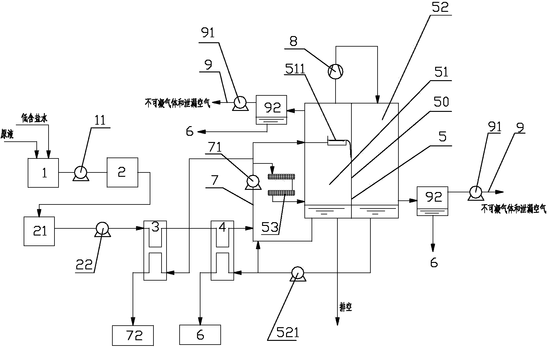
[0059] This embodiment provides a mechanical vapor recompression evaporation system, the flow and structure of the mechanical vapor recompression evaporation system are as follows Figure 1 to Figure 4 As shown, it includes a raw liquid storage tank 1 , a preprocessor 2 , a first heat exchanger 3 and a second evaporator 4 , an evaporative condensation device 5 and a condensed water recovery tank 6 connected in sequence according to the liquid flow direction.

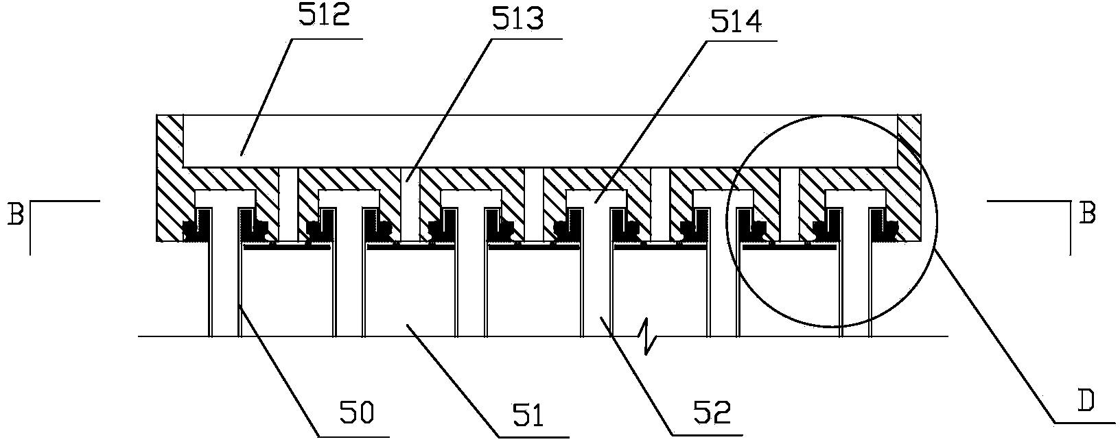
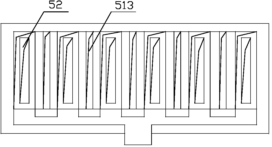
[0060] The structure of evaporative condensation device 5 is as Figure 2-Figure 4 As shown, the evaporation and condensation device 5 includes an evaporator 51 and a condenser 52 separated by a plurality of polymer films 50 and a heater 53 that provides heat to the evaporator 51 . The evaporator 51 is also provided with an overflow liquid distributor 511 , a liquid pan 512 , a long liquid slit 513 , and an air intake channel 514 , and the overflow liquid distributor 511 is provided with a liquid distribution plate 5110 ...

Embodiment 2

[0074] This embodiment provides an energy-saving method for a mechanical vapor recompression evaporation system. Under the condition of the same evaporation Q value, according to the formula: Q=K×A×ΔT and Pc=C×Q×ΔT (wherein, Q is the evaporation amount, K is the heat transfer coefficient, A is the evaporation surface area, and △T is the heat transfer coefficient. Heat temperature difference, Pc is fan power consumption, C is fan coefficient), can increase the effective evaporation area A of the evaporator, reduce the heat transfer temperature difference ΔT of the evaporator, and the decrease of ΔT directly leads to the decrease of Pc.

[0075] Among them, the heat transfer temperature difference of the evaporator is reduced to 2-3°C. The reduction of the heat transfer temperature difference can reduce the energy consumption and cost of the fan, thereby reducing the energy consumption and investment cost of the MVR system. Due to the low price of the polymer film, although the...

Embodiment 3

[0077] This embodiment provides an energy-saving method for a mechanical vapor recompression evaporation system, that is, to transfer the working point of the mechanical vapor recompression evaporation system to an environment with negative pressure and a temperature range of 40-70°C.

[0078] Under the same heat transfer temperature difference, the pressure difference between the evaporator and the condenser is reduced, which reduces the power consumption of the fan, thereby reducing the energy consumption and investment cost of the MVR system.


PUM

PropertyMeasurementUnit
Thermal conductivityaaaaaaaaaa
Thicknessaaaaaaaaaa
Thermal conductivityaaaaaaaaaa

Abstract

The invention discloses a mechanical steam recompressing evaporation system and an energy saving method, and belongs to the technical fields of evaporation and energy conservation. The mechanical steam recompressing evaporation system is designed for solving the problems that an existing MVR system forms scales, corrodes, and is high in manufacturing cost and energy consumption in the industrial wastewater treatment and recover processes. The evaporation system comprises a stock solution storage tank, a pretreater, a heat exchange device, an evaporation and condensation device and a condensed water recovery pond, wherein the stock solution storage tank, the pretreater, the heat exchange device, the evaporation and condensation device and the condensed water recovery pond are sequentially connected in the flowing direction of liquid. The evaporation and condensation device comprises a plurality of evaporators, a plurality of condensers and an electromagnetic induction heater, the evaporators and the condensers are arranged in a separated mode through a plurality of thin polymer films; the heat exchange device is connected with the evaporators through a circulating liquid system, the evaporators are connected with the condensers through fans, and the condensers are connected with the condensed water recovery pond through the heat exchange device. The invention further provides the energy-saving method of the evaporation system. The thin polymer films are used for replacing metal films of the existing MVR system to manufacture the evaporation and condensation device, the evaporation and condensation device has the equivalent heat transfer effect as the metal-film evaporation and condensation device, and the problems of corrosion and scale forming on the surfaces of the evaporators are solved.

Description

technical field [0001] The invention relates to a mechanical vapor recompression evaporation system and an energy-saving method, belonging to the technical field of evaporation and energy conservation. Background technique [0002] MVR is the abbreviation of Mechanical Vapor Recompression technology (Mechanical Vapor Recompression), which is an energy-saving technology that reuses the energy of the secondary steam generated by itself, thereby reducing the demand for external energy. Mechanical vapor recompression is a kind of evaporation process, which is to recompress the secondary steam generated by the evaporator by mechanical means, so as to increase its pressure and temperature, increase the internal energy, and then return to the original evaporator to replace raw steam as a heat source. The latent heat in the secondary steam can be fully utilized to achieve the purpose of energy saving. Mechanical vapor recompression technology is widely used in chemical, pharmaceuti...

Claims


Application Information

Patent Timeline
IPC IPC(8): B01D1/28B01D1/30
CPCY02P70/10
Inventor 邬扬善
Owner BEIJING OTC ENERGY & ENVIRONMENT ENGINEERING PUBLIC LIMITED COMPANY
Why Eureka
Eureka Blog
Learn More