
Continuous sand filtration apparatus

A continuous type, sand filtration technology, applied in the direction of filtration separation, filtration circuit, gravity filter, etc., can solve the problems of unstable water output and water quality, and achieve the effect of stable water volume, stable water quality and strong adaptability

Active Publication Date: 2012-03-28
罗文峰
View PDF3 Cites 8 Cited by
  • Summary
  • Abstract
  • Description
  • Claims
  • Application Information

AI Technical Summary

Problems solved by technology

[0004] The purpose of the present invention is to provide a continuous type sand filter equipment to solve the technical problems of unstable water output and unstable water quality in the fixed filter bed type sand filter device in the prior art

Method used

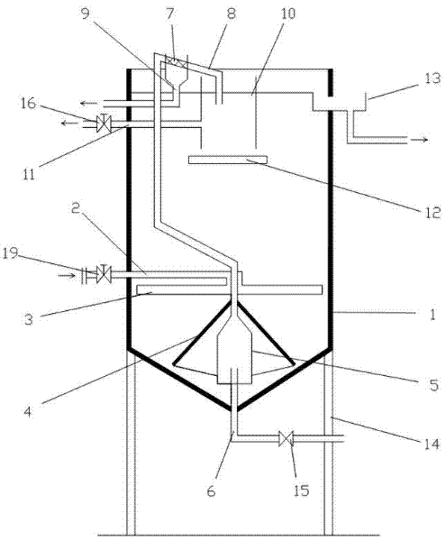
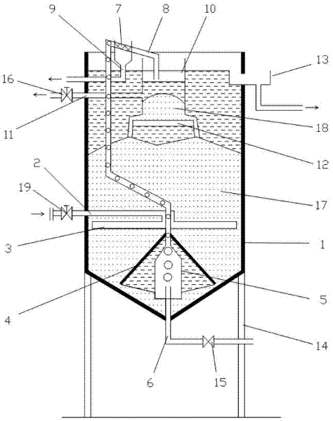
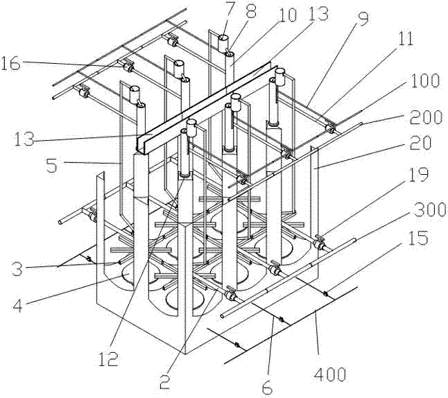

Image

  • Continuous sand filtration apparatus
  • Continuous sand filtration apparatus
  • Continuous sand filtration apparatus

Examples


Embodiment 1

[0038] Please refer to figure 1 and figure 2 , a continuous sand filter equipment, including a cylinder 1 and a sand filter device, the bottom of the cylinder 1 is conical. In the present invention, the upper part of the cylinder 1 is a straight wall, and the lower part is a cone, but the upper part of the cylinder 1 of the present invention is not limited thereto. The sand filter device is arranged in the cylinder body 1, wherein the sand filter device includes a sand bed 17, an air inlet pipe 6, an air lift pipe 5, a water filtration flow channel 7, a raw water distribution deflector 3, a grit chamber 10, and a floating support plate 12 and clean water outlet weir 13:

[0039] The sand bed 17 is used for filtering sewage, the sand bed 17 is located in the cylinder body 1, and the sand bed 17 is formed by filter sand. That is, filter sand is injected into the cylinder body 1 , and the upper plane of the filter sand (that is, the upper plane of the sand bed 17 ) is below t...

Embodiment 2

[0054] Please refer to image 3 , a continuous type sand filter equipment, including a filter tank and several sand filter devices, the sand filter device in this embodiment has the same structure as the sand filter device in Embodiment 1, therefore, the labels of the internal parts of the sand filter device in this embodiment What is indicated in Embodiment 1 is used, and will not be described in detail below. The bottom of the filter tank includes several cone-shaped bottoms, which are evenly arranged at the bottom of the pool. Of course, it is also possible that some cone-shaped bottoms are not evenly arranged at the bottom of the pool. The present invention does not limit this. For ease of use and the convenience of maintenance, in this embodiment, several conical bottoms are evenly arranged at the bottom of the filter tank. Several columns 20 are also arranged in the filter tank, and the columns 20 are arranged between each conical bottom to prevent the filter sand from ...


PUM


Abstract

The invention relates to a continuous sand filtration apparatus. The apparatus comprises a cylindrical shell and a sand filtration device, wherein the cylindrical shell has a tapered bottom, and the sand filtration device which is arranged in the cylindrical shell comprises: a sand bed which is positioned in the cylindrical shell and is formed by filtration sand; a clean water outlet weir which is arranged on the upper part of the cylindrical shell; a raw water distributing director which is arranged on the lower part of the sand bed and is connected with a raw water inlet tube; a sand settling cylinder which is arranged on the upper end of the cylindrical shell and has no bottom, wherein the side surface of the sand settling cylinder is provided with a water outlet which is connected with a first sewage outlet tube; a floatation supporting plate which is arranged under the sand settling cylinder; an air lifting tube which is arranged on the bottom of the cylindrical shell and traverses the raw water distributing director to enter the sand settling cylinder; an air inlet tube which is positioned on the tapered bottom of the cylindrical shell and is inserted into the air lifting tube; and a water filtering channel which is connected with the upper end of the air lifting tube, wherein the lower end of the water filtering channel is connected to the inside of the sand settling cylinder through a sand guiding tube. The apparatus of the invention has the advantages of no need of backwashing, stable outlet water quality, stable water volume, realization of controlling pipelines by control valves, simple structure, easy operation, and strong adaptability.

Description

technical field [0001] The invention relates to water treatment equipment, in particular to a continuous sand filter equipment. Background technique [0002] Existing water (including sewage, drinking water, etc.) treatment equipment, except for their differences in process flow, equipment structure and filter media, most of their filter beds are fixed, and the water treatment equipment of fixed filter beds are all There is a feature that it must be stopped regularly to clean and remove the intercepted matter on the rate bed. Therefore, periodic shutdown to clean the filter medium will inevitably have a certain impact on the productivity and operating efficiency of water treatment. In order to overcome this shortcoming, the unit cluster is often formed by adding equipment, and the production mode of some equipment running and some equipment shutting down for cleaning is relatively speaking, which not only increases equipment investment, but also wastes water resources, and i...

Claims


Application Information

Patent Timeline
IPC IPC(8): B01D24/36B01D24/46B01D36/00
Inventor 罗文峰
Owner 罗文峰
Learn More