Pressure kneading machine

A kneader and hydraulic technology, applied in mixers, mixers with rotary stirring devices, mixer accessories, etc., can solve the problems of materials that cannot be compacted, and achieve the effects of increasing fluidity, reducing resistance, and improving kneading efficiency.

Inactive Publication Date: 2012-03-28
范慧君
View PDF5 Cites 5 Cited by
  • Summary
  • Abstract
  • Description
  • Claims
  • Application Information

AI Technical Summary

Problems solved by technology

[0004] Purpose of the invention: to overcome the defect that materials cannot be compacted in traditional kneaders, and to provide a pressurized kneader that can improve the kneading effect

Method used


Image

  • Pressure kneading machine
  • Pressure kneading machine
  • Pressure kneading machine

Examples


Embodiment 1

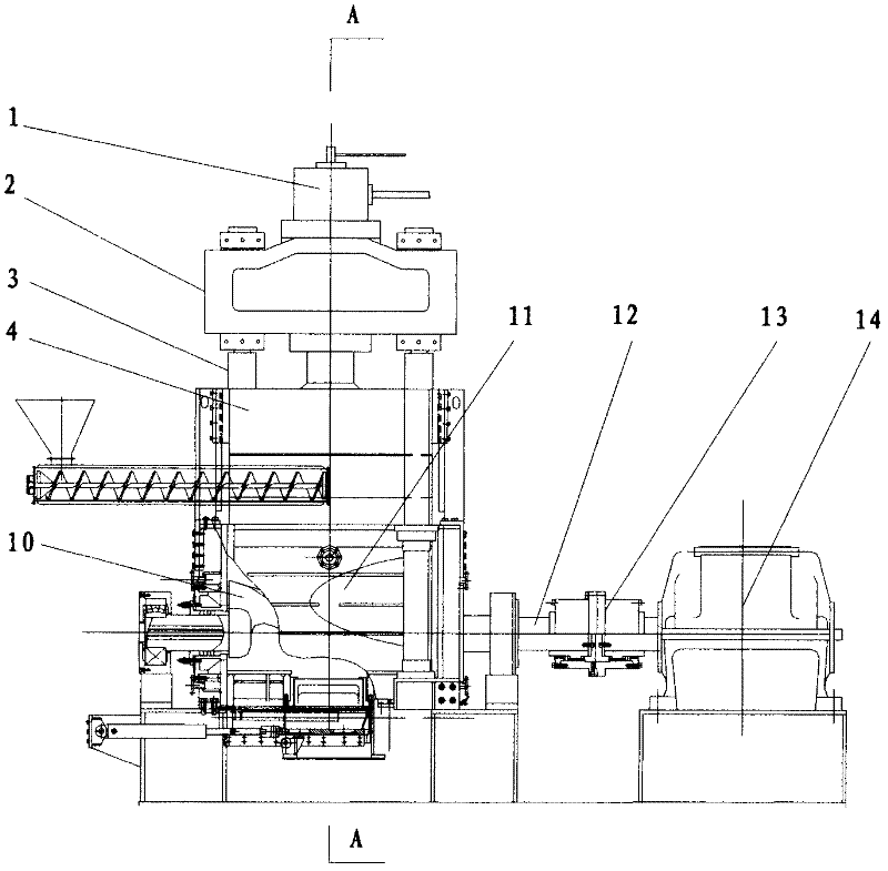
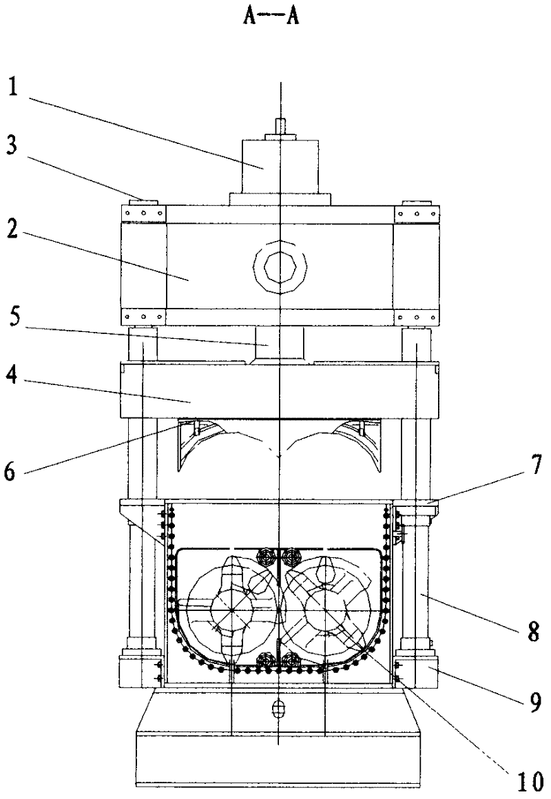
[0018] The stroke of the pressure pot 4 moving up and down is 30cm, and there is a sealing ring 6 between the pressure pot cover 4 and the pot body assembly 11 . The hydraulic drive device has a column 3 and a matching hydraulic cylinder 8, which are arranged on the periphery of the pot body assembly 11. There is a steam heating device in the outer wall of the pot body assembly 11 .

Embodiment 2

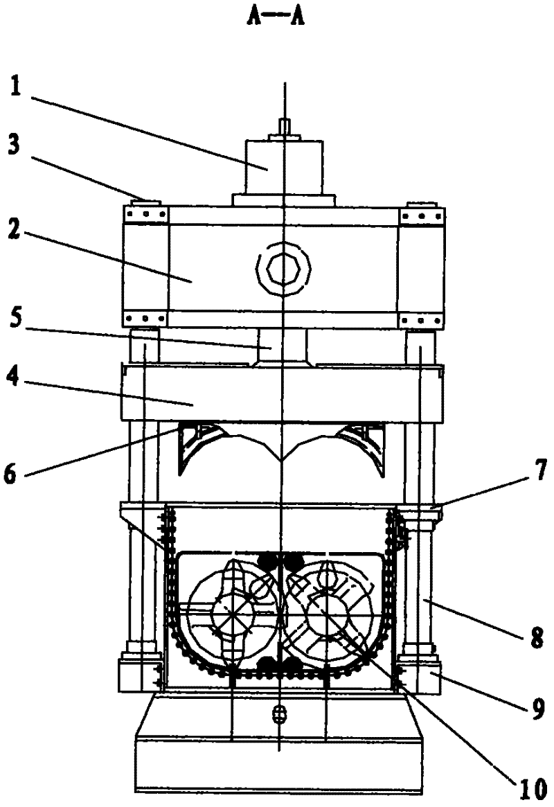
[0020] The stroke of the pressurized pot cover 4 moving up and down is 60cm, and a sealing ring 6 is arranged between the pressurized pot cover 4 and the pot body assembly 11 . The hydraulic drive device has four columns 3 and four matching hydraulic cylinders 8, which are arranged in a rectangular shape on the periphery of the pot body assembly 11. There is a thermal oil heating device in the outer wall of the pot body assembly 11 .

[0021] In the above-mentioned embodiments 1 and 2, when the kneader is working, the stirring shaft 12 and the stirring knife 10 drive the material to turn over in the pot body assembly 11, and the piston rod 5 of the hydraulic drive device drives the pressurized pot cover 4 to move up and down to adjust the material room for movement, exerting additional pressure on the material. At the same time, the heating device heats the material, which increases the temperature of the kneaded material, increases the fluidity of the material, reduces the r...


PUM


Abstract

The invention provides a pressure kneading machine, which comprises a pressure pot cover, a hydraulic driving device, a pot body assembly, a stirring shaft, a stirring knife and other necessary parts of the kneading machine. The hydraulic driving device has a piston rod, an upright post, a hydraulic cylinder upper supporting ear, a hydraulic cylinder, and a hydraulic cylinder lower supporting ear; the hydraulic driving device is connected with the pressure pot cover and controls the pressure pot cover to move up and down; the up and down movement stroke of the pressure pot cover is 10 to 100 centimeters; and a sealing ring is arranged between the pressure pot cover and the pot body assembly. The stirring shaft and the stirring knife are arranged in the pot body assembly, and a steam or hot oil heating device is arranged in the outer wall of the pot body assembly. According to design requirements, when the kneading machine operates, the stirring shaft drives a material to overturn in the pot body assembly, the hydraulic driving device drives the pressure pot cover to move up and down to reduce the free movement space of materials and to apply extra pressure onto the material to compact the material; meanwhile, the heating device heats the material to rise the temperature of the kneaded material and increase the flowability of the material, thereby reducing resistance during kneading and improving kneading efficiency.

Description

technical field [0001] The invention relates to a mixing and kneading machine, in particular to a pressurized mixing and kneading machine which adopts a hydraulic drive device to movably connect a pressurized pot cover. Background technique [0002] Usually, the kneader is composed of a kneading part (stirring shaft and stirring knife), a pot assembly part (or a kneader shell part), a transmission system and an electric control system. For ordinary kneading machines, the pot body and pot cover are connected to the atmosphere in an open connection or in a fixed space, which is not feasible for materials with high airtightness requirements or materials with high compactness requirements. [0003] The description of the patent application No. 200980103471.2 discloses "a kneading degree adjusting device, an extruder, and a continuous kneading machine". Kneading adjustment device. The kneading screw has a cylindrical section formed at a predetermined position, kneads the materi...

Claims


Application Information

Patent Timeline
Patent Type & Authority Applications(China)
IPC IPC(8): B01F7/02B01F13/06B01F15/06
Inventor 范靖华汤俊
Owner 范慧君
Why Eureka
Try Eureka