Electric stepless flow regulating valve

A flow regulating valve, stepless technology, applied in the field of liquid flow control valves, electric stepless flow regulating valves, can solve the problems of poor regulation linearity, complex structure of flow regulating valves, etc., to ensure the linearity of flow regulation and ensure linearity degree, the effect of improving stability

Pending Publication Date: 2022-08-05
XIAN AEROSPACE PROPULSION INST
View PDF0 Cites 0 Cited by
  • Summary
  • Abstract
  • Description
  • Claims
  • Application Information

AI Technical Summary

Problems solved by technology

[0003] The technical problem to be solved by the present invention is: to overcome the deficiencies of the prior art, and to solve the problems of complex structure and poor adjustment linearity of the existing flow regulating valve

Method used


Image

  • Electric stepless flow regulating valve
  • Electric stepless flow regulating valve
  • Electric stepless flow regulating valve

Examples


Embodiment 1

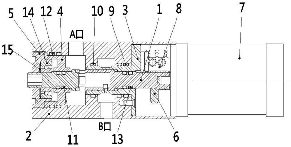
[0039] The invention provides an electric stepless flow regulating valve, which is directly driven by a stepping motor, rotates the valve stem, and shields the throttle window to realize the flow regulating function. The special window structure design ensures the better linearity of the electric stepless flow control valve. The invention has the characteristics of good linearity, compact structure, reliable action, good sealing performance and the like.

[0040] Specifically, the electric stepless flow regulating valve includes a valve stem 1, a valve body 2, a bushing 3, an unloading ring 4, a bearing seat 5, a micro switch 8, a trigger sleeve 6 and a stepping motor 7;

[0041] The valve stem 1 runs through the entire flow regulating valve, the left side penetrates the unloading ring 4, the bearing 14 and the bearing seat 5, the right side penetrates the bushing 3 and the trigger sleeve 6; the leftmost end is provided with an inner hexagon for manual operation The valve ste...

Embodiment 2

[0053] like figure 1 As shown, an electric stepless flow control valve is mainly composed of a valve stem 1, a valve body 2, a bushing 3, an unloading ring 4, a bearing 14, a bearing seat 5, a micro switch 8, a trigger sleeve 6 and a stepper Motor 7 is composed.

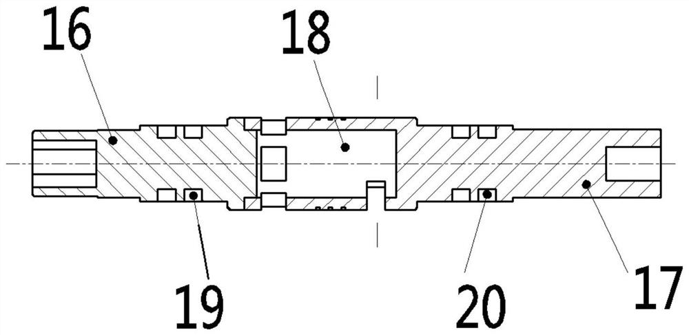
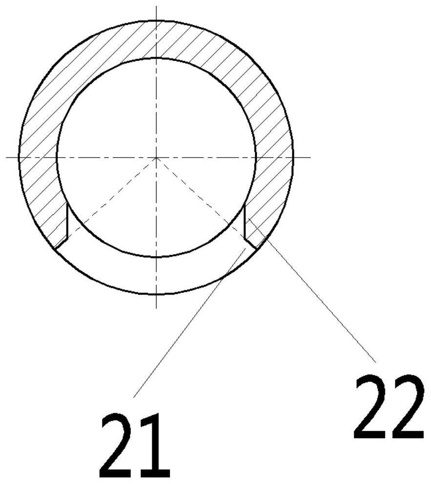
[0054] The structure of the electric stepless flow control valve is as follows: the valve stem 1 penetrates the entire flow control valve, the left side penetrates the unloading ring 4, the bearing 14 and the bearing seat 5, and the right side penetrates the bushing 3 and the trigger sleeve 6; The inner hexagon is used to manually operate the rotation of the valve stem 1; the rightmost end is provided with a flat groove, which is connected with the output shaft of the stepping motor 7; the left side 16 of the valve stem and the right side 17 of the valve stem are connected by welding, and are formed inside the right side after being connected. In the flow channel space with windows, there are four windows on the lef...


PUM


Abstract

An electric stepless flow regulating valve comprises a valve rod (1), a valve body (2), a lining (3), an unloading ring (4), a bearing structure, a trigger sleeve (6), a stepping motor (7) and a microswitch (8). The stepping motor (7) is installed at one end of the valve body (2) and connected with one end of the valve rod (1). The lining (3), the unloading ring (4) and the bearing structure are all installed in the valve body (2), and the other end of the valve rod (1) sequentially penetrates through the lining (3), the unloading ring (4) and the bearing structure. The valve body (2) is provided with an A opening ring cavity and a B opening ring cavity, and a lining window is locally arranged on the lining (3). A runner space (18) with windows is arranged in the valve rod (1), a part of the windows are communicated with the A-port ring cavity, and the runner space (18) is communicated with the B-port ring cavity through rotation of the valve rod (1); the trigger sleeve (6) is used for feeding back the position state of the valve rod (1), and the outside controls the stepping motor (7) through the microswitch (8).

Description

technical field [0001] The invention relates to an electric stepless flow control valve, in particular to an electric stepless flow control valve with good linearity, which can be used as a liquid flow control valve of a fluid control system to realize precise control of medium flow, and belongs to the flow control valve technical field. Background technique [0002] The electric stepless flow control valve in the prior art generally has a complex transmission mechanism. One solution is to convert the rotary motion of the motor into a linear motion, and adjust the flow rate by opening and closing the valve port; the control valve of the other solution adopts a ball valve structure. The motor directly drives the ball valve stem to rotate; the flow is adjusted by opening and closing the valve port. The existing technical solution of the regulating valve has poor flow adjustment linearity, cannot be applied to ordinary open-loop control systems, and has a large structure size. ...

Claims


Application Information

Patent Timeline
Patent Type & Authority Applications(China)
IPC IPC(8): F16K31/04F16K41/02F16K27/00
CPCF16K31/04F16K41/02F16K27/00
Inventor 赵双龙雷小飞沙超曾维亮孙磊刘小明刘莎莎
Owner XIAN AEROSPACE PROPULSION INST
Why Eureka
Try Eureka