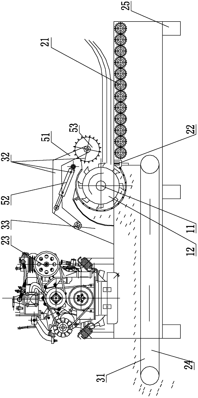
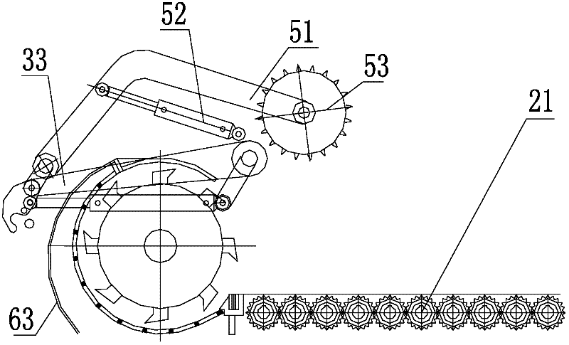
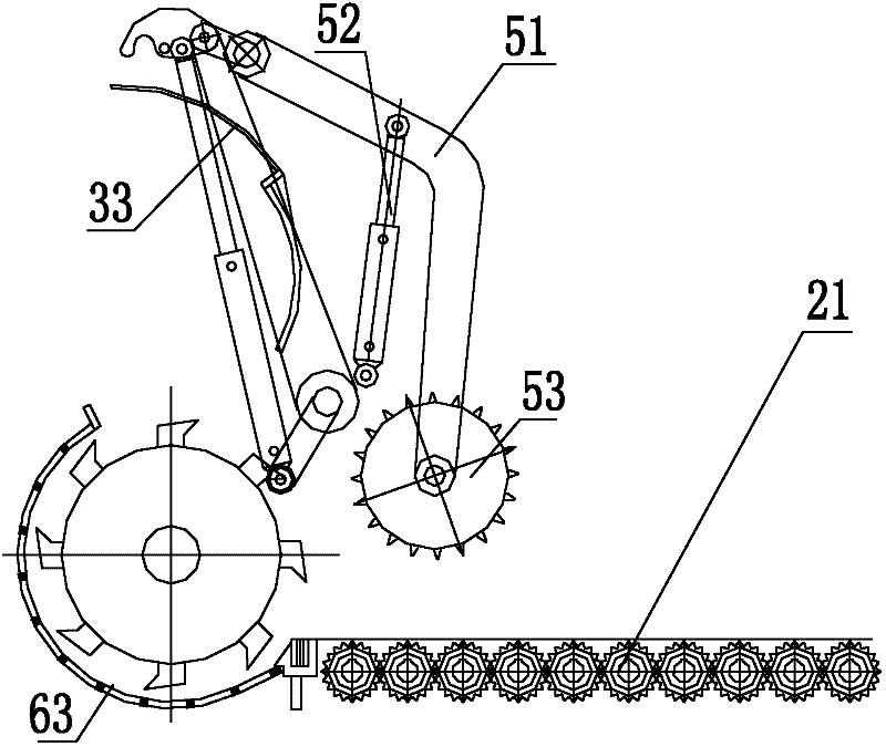
Plant crusher with spiral fly cutter drum
A technology of crushers and flying knives, which is applied in the direction of grain processing, etc., can solve the problems of crushing, unreasonable blade design, time-consuming and labor-intensive problems, and achieve the effect of saving time and cost
- Summary
- Abstract
- Description
- Claims
- Application Information
AI Technical Summary
Problems solved by technology
Method used
Image
Examples
Embodiment 1
[0025] Such as Figure 9 As shown: the side cross section of the spirally arranged flying knives is L-shaped, one end of the knife seat 13 of all the flying knives is fixed on the surface of the knife drum, and the fixed end of the knife seat of each row of flying knives along the central axis of the knife drum is fixed on the knife drum On the same straight line on the surface, the knife edge 14 of the flying knife is an oblique knife edge, and the knife edge slope of each flying knife is the same, and for two adjacent flying knives, the starting end of any flying knife edge is adjacent to the starting end of the flying knife. The ends of the knife edge join so that the edge is in a straight line. In this way, when the flying knives are distributed on the knife drum, although the knife seat part of the flying knives does not present a spiral distribution, the knife edge of the flying knives still forms a spiral distribution. This structure is more suitable for crushing and cu...
Embodiment 2
[0027] Such as Figure 10 As shown: the surface of the knife drum is provided with several groups of flying knife sets 15 with cross-shaped side cross-sections formed by connecting four knife seat parts with L-shaped flying knives in side cross-section. The flying knives in the flying knife group are as follows: Arranged in a clockwise direction or counterclockwise direction at the same time, the side cross-section of the overall structure is similar to a "Swastika" shape, but the angle at the connection is not 90 degrees, and the tool holder part is connected to form a circular through hole in the center structure, several groups of flying knives are sleeved and fixed on the knife drum through circular through holes, and compared with the flying knife group on the left side of any flying knife group, the flying knife group rotates slightly forward or backward. The flying knives of adjacent flying knife groups are slightly staggered from each other. The structure can be cut f...
Embodiment 3
[0029] Such as Figure 11 As shown: there are several groups of flying knives with L-shaped side cross-sections on the surface of the knife drum. Completely staggered and not connected, the bending surface of the knife seat not connected to the knife drum is a bending surface that is tangent to the surface of the knife drum and points clockwise or counterclockwise at the same time, and the knife seat on the knife drum is in a spiral shape Distribution, the bending surface of each knife seat is fixed with flying blade 17 by bolt 16. The structure of this embodiment cuts mainly at tree roots.
[0030] The above arrangements can be applied to different situations. By selecting different knife drums for different materials, large materials and branches can be broken, and at the same time, sediment and small stones are not easy to damage the flying knife.
PUM
 Abstract
Description
Claims
Application Information
 - R&D
- Intellectual Property
- Life Sciences
- Materials
- Tech Scout
- Unparalleled Data Quality
- Higher Quality Content
- 60% Fewer Hallucinations
Browse by: Latest US Patents, China's latest patents, Technical Efficacy Thesaurus, Application Domain, Technology Topic, Popular Technical Reports.
© 2025 PatSnap. All rights reserved.Legal|Privacy policy|Modern Slavery Act Transparency Statement|Sitemap|About US| Contact US: help@patsnap.com


