Electric automobile chassis of employing live axle hub motor as driving wheel

A technology of electric vehicles and driving wheels, which is applied in the field of electric vehicles, can solve the problems of inconvenient mass production and daily maintenance, the crankshaft cannot be pulled out from the motor, and the inconvenient loading and unloading of driving wheels, etc., so as to achieve simple structure and light mobility , Easy to install and use

Inactive Publication Date: 2012-03-28
河南超微电动汽车有限公司
View PDF0 Cites 8 Cited by
  • Summary
  • Abstract
  • Description
  • Claims
  • Application Information

AI Technical Summary

Problems solved by technology

But the hub motors currently used in electric vehicles are all dead shaft hub motors, and the crankshaft cannot be pulled out from the motor
Because its stator is directly fixed on the wheel shaft, the wheel hub rotor located on the periphery of the stator and also used as the motor casing is also fixed on the wheel shaft through the bearings on both sides, making the automobile wheel shaft an indispensable installation base for the wheel hub motor. The wheel hub motor with this structure cannot be disassembled from the wheel shaft as a whole after the components are assembled. Once removed, the stator and rotor of the hub motor will lose the installation base and be misplaced and scattered.
The use of such hub motors in electric vehicles makes it very inconvenient to load and disassemble the driving wheels, which is not convenient for mass production and daily maintenance; in addition, all the wires of this hub motor are passed through the threading holes inside the car wheel shaft or other places. In vitro, connecting with the exposed controller wire connector not only adds a manual connection process, but also reduces the reliability of the electrical connection

Method used


Image

  • Electric automobile chassis of employing live axle hub motor as driving wheel
  • Electric automobile chassis of employing live axle hub motor as driving wheel
  • Electric automobile chassis of employing live axle hub motor as driving wheel

Examples


Embodiment Construction

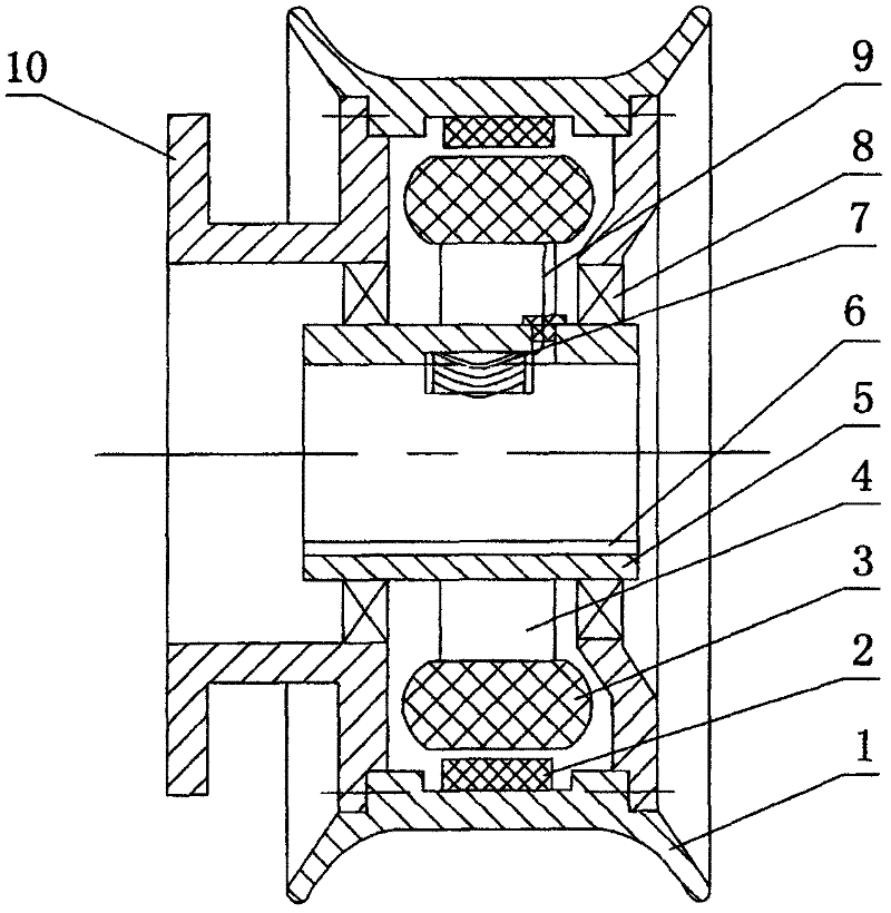
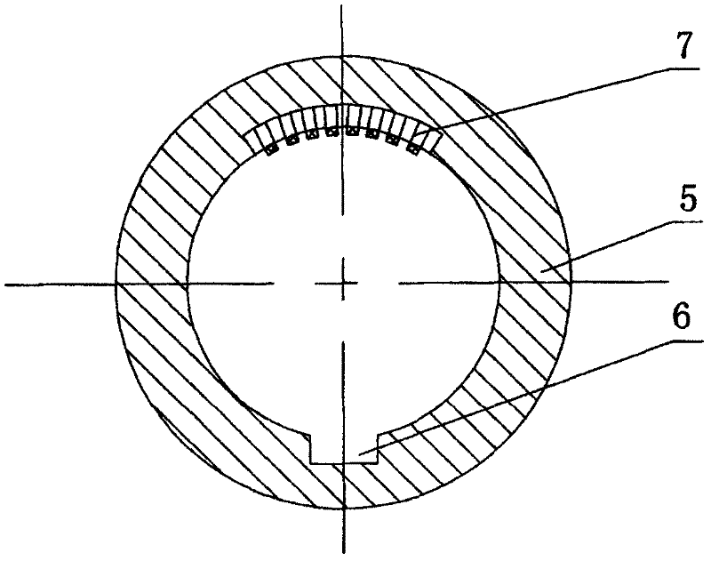
[0018] figure 1 , figure 2 The shown live shaft hub motor includes a shaft sleeve 5, and a stator is fixed on the outer wall of the shaft sleeve. The stator includes a coil 3 and a stator bracket 4 installed on the shaft sleeve. Bearing 8, the hub rotor 1 located on the periphery of the stator and also used as the motor casing is installed on the bearing 8, and the inner wall of the hub rotor has a magnetic steel 2. The inner wall of the shaft sleeve is provided with an axially penetrating keyway 6, and the middle section of the inner wall of the shaft sleeve is provided with a sinking groove at the position opposite to the keyway. The lead wire hole, the sinker is embedded with an elastic electrical connection terminal 7, the motor coil lead wire 9 passes through the wire through hole and is electrically connected with the elastic electrical connection terminal 7, the elastic electrical connection terminal 7 is an elastic pressure contact terminal, and its elastic pressure ...


PUM


Abstract

The invention relates to an electric automobile chassis of employing a live axle hub motor as a driving wheel, comprising a battery pack, a controller, a hub motor and an axle, wherein the hub motor further comprises axle sleeves; stators are fixedly arranged on the outer walls of the axle sleeves; bearings are arranged on the outer walls of the axle sleeves on two sides of each stator, respectively; hub rotors are arranged on the bearings; the driving wheel is inserted into corresponding position of the axle through the axle sleeves; the inner walls of the axle sleeves are provided with a key slot which axially penetrates, and a first elastic electric connection terminal which is electrically connected with a motor coil; the axle is provided with a key in coordination with the key slot and a second elastic electric connection terminal which is electrically connected with the controller correspondingly; the first elastic electric connection terminal and the second elastic electric connection terminal are electrically connected automatically after the driving wheel is installed at proper position so that the circuit becomes simple and reliable, and simultaneously the electric automobile chassis is conveniently produced, installed, used and overhauled.

Description

technical field [0001] The invention relates to the technical field of electric vehicles, in particular to an electric vehicle chassis using a live-shaft hub motor as a driving wheel. Background technique [0002] There are three main driving methods for electric vehicles at present: 1. The front drive mode in which the front mid-mounted motor directly drives the front wheels through the gearbox and differential; 2. The rear mid-mounted motor directly drives the rear wheel through the gearbox and differential. 3. Use the hub motor to directly drive the wheel hub motor drive mode. The electric vehicle that uses the hub motor directly as the driving wheel, the car tire is directly installed on the hub rotor of the hub motor, and combined with the hub motor to form the driving wheel to directly drive the vehicle, which saves the gearbox and differential, and improves the energy. usage efficiency. However, the hub motors currently used in electric vehicles are all dead-shaft h...

Claims


Application Information

Patent Timeline
Patent Type & Authority Applications(China)
IPC IPC(8): B60K7/00B60K17/12
Inventor 董建国
Owner 河南超微电动汽车有限公司
Why Eureka
Try Eureka