
Vertical landing track design method for unmanned aerial vehicle

A design method and technology for unmanned aerial vehicles, applied in the field of flight control, can solve problems such as difficulty in grasping the safety margin of the unmanned aerial vehicle, elevator control margin, the pitch angle of the unmanned aerial vehicle exceeding the safe range, and aircraft accidents, so as to avoid the landing accuracy. and safety, improve rationality and design efficiency, and improve the effect of operating margin

Inactive Publication Date: 2013-07-24
BEIHANG UNIV
View PDF7 Cites 0 Cited by
  • Summary
  • Abstract
  • Description
  • Claims
  • Application Information

AI Technical Summary

Problems solved by technology

Traditional landing trajectories only give altitude (or descent speed) and airspeed commands, often do not give information on pitch angle, angle of attack, elevator, and throttle, and it is difficult for control law designers to grasp the safety margin of the UAV and the control parameters of the elevator. The design process of maneuvering margin and landing trajectory requires experience trial and error, the design is cumbersome and depends on rich experience
The lift speed and airspeed command in the leveling phase are linear functions of height. Due to external interference and errors in the closed-loop control of lift speed, it is easy to cause height deviation to affect the lift speed command, which will cause the actual touchdown point of the UAV to be far from the ideal touchdown point. It may cause the pitch angle of the UAV to exceed the safe range, causing aircraft accidents
Many advanced UAV landing control algorithms control the height and airspeed, and often take into account the descent speed and pitch angle to ensure that the UAV lands smoothly according to the determined state reference, while the traditional landing trajectory and its design method cannot meet the requirements.

Method used


Image

  • Vertical landing track design method for unmanned aerial vehicle
  • Vertical landing track design method for unmanned aerial vehicle
  • Vertical landing track design method for unmanned aerial vehicle

Examples


Embodiment Construction

[0096] The present invention will be further described in detail with reference to the accompanying drawings and embodiments.

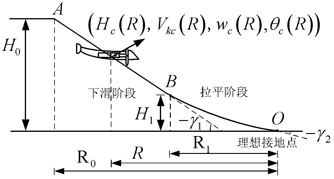
[0097] The present invention proposes a design method for the longitudinal landing trajectory of the UAV, such as figure 1 As shown, the starting point of the drone's descent is A, the starting point of leveling is B, and the ideal touchdown point is O. The height H of the sliding starting point A 0 , the height H of leveling starting point B 1 and the track angle of the glide phase γ 1 Given by the flight requirements of the drone. The height H of the ideal grounding point 2 Equal to the height of the center of gravity of the drone parked on the ground, the track angle of the ideal touchdown point γ 2 Permissible descent speed to ground according to w 2 Sure. The longitudinal landing trajectory of the drone takes the distance to fly at the current position of the drone R as an independent variable, and is determined by the altitude command H ...


PUM


Abstract

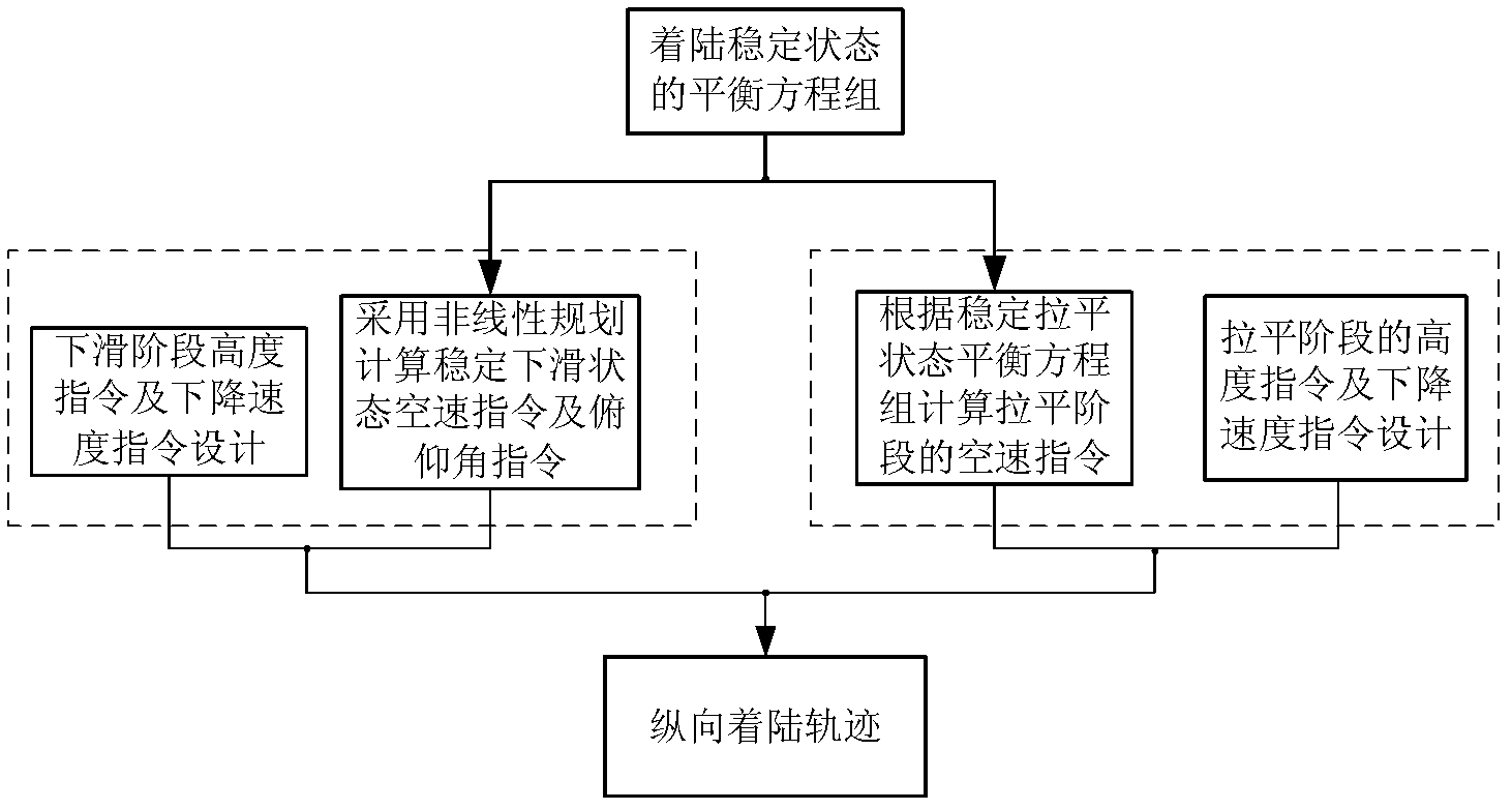
The invention provides a vertical landing track design method for an unmanned aerial vehicle, which belongs to the field of flight control and comprises the following steps of: 1, building a balance equation of the unmanned aerial vehicle landing stability state according to the kinematics relationship of the unmanned aerial vehicle; 2, adopting a non-linear plan method for designing the verticallanding track of the unmanned aerial vehicle in a glissade stage; 3, designing the height track in an index form in a leveling stage and solving the non-linear equation to obtain the vertical landingtrack of the unmanned aerial vehicle according to the designed track angle trimming value and the elevation instructions in the leveling stage; and 4, integrating the landing tracks in the glissade stage and the leveling stage to obtain the vertical landing track of the whole unmanned aerial vehicle. The method has the advantages that the safety margin of the incidence angle and the operation margin of an elevator are improved, the precise and safe landing of the unmanned aerial vehicle is convenient to guide, the method is applicable to the landing control algorithm considering all of the height, the pitch angle and the descending speed, in addition, the landing performance is fully analyzed, and mathematic software is adopted for effective design to avoid the traditional experience trial and error.

Description

technical field [0001] The invention belongs to the field of flight control, and in particular relates to a design method for a longitudinal landing trajectory of an unmanned aerial vehicle. Background technique [0002] Due to the advantages of low cost and high performance, UAVs are widely used in military and civilian applications. According to the statistics of drone accidents, drones are most prone to accidents during the landing phase, and automatic landing is a key technology related to the safe recovery of drones. [0003] The landing process of the wheeled take-off and landing UAV can be divided into the glide phase and the leveling phase. The glide phase requires the UAV to slide down the trajectory determined by the fixed track angle at a specific airspeed. When the UAV descends to the starting point of the leveling When the altitude is high, the UAV’s descent speed is required to gradually decrease to the allowable ground descent speed to prevent the UAV from hi...

Claims


Application Information

Patent Timeline
Patent Type & Authority Patents(China)
IPC IPC(8): G05D1/00B64F5/00
Inventor 刘智王勇
Owner BEIHANG UNIV
Learn More