Feeding cabin with composite air ventilation structure

A ventilation structure and feeding bin technology, applied in the direction of containers, packaging, transportation and packaging, etc., can solve the problems of not giving the structural characteristics and dimensions of the main part of the container and the bottom unloading device, etc., to improve the mass flow rate of the discharge , smooth discharge and compact structure

Active Publication Date: 2012-03-28
EAST CHINA UNIV OF SCI & TECH
View PDF5 Cites 4 Cited by
  • Summary
  • Abstract
  • Description
  • Claims
  • Application Information

AI Technical Summary

Problems solved by technology

However, this patent only provides the connection and sealing method between the unloading device and the main part, and neither provides the structural features and dimensions of the main part of the container and the bottom unloading device, nor does it aim at promoting the discharge of the silo and eliminating the discharge. Propose relevant ventilation layout plans for problems such as poor material flow

Method used


Image

  • Feeding cabin with composite air ventilation structure
  • Feeding cabin with composite air ventilation structure

Examples


Embodiment 1

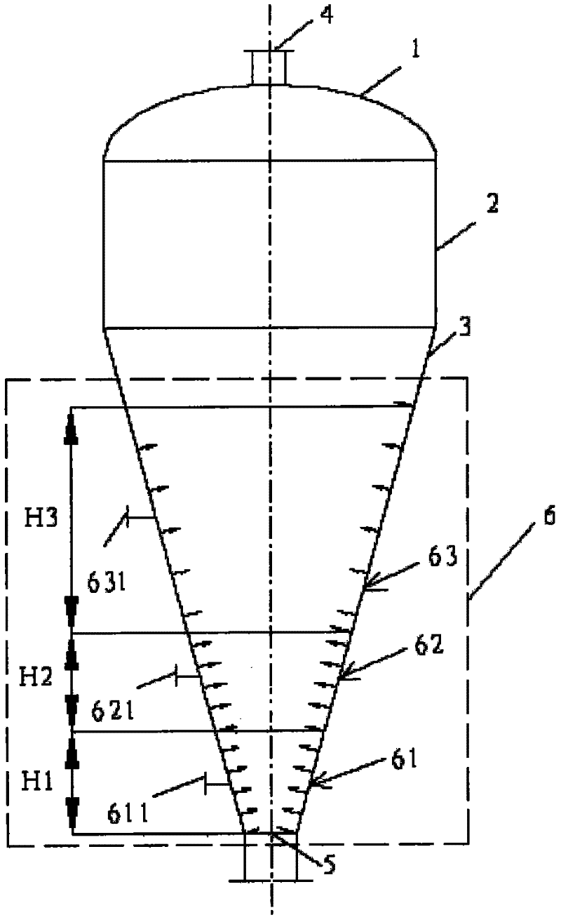
[0025] Such as figure 1 Described, the feeding bin with compound ventilation structure of the present invention comprises a cone angle and is the conical container 3 of 30 °, and the bottom of this conical container 3 has a discharge opening 5, and the diameter of this discharge opening 5 is 300mm. A cylindrical container 2 connected with the conical container 3 is arranged above the conical container 3 , and a sealing head 1 is arranged above the cylindrical container 2 , and a feed inlet 4 is provided on the sealing head 1 .

[0026] On the inner wall of the conical container 3 is an inflator 6 . The inflation device 6 includes a first inflation mechanism 61 near the position of the discharge opening 5, the first inflation mechanism 61 extends upwards to a height H1 based on the discharge opening, and the height H1 is 0.87 times the diameter of the discharge opening 5, That is, H1=261mm. An air inlet 611 is provided on the side wall of the conical container 3 correspondin...

Embodiment 2

[0033] The difference between this embodiment and Embodiment 1 lies in that the cone angle of the conical container 3 is 40°, and the diameter of the discharge opening 5 is 200 mm. The height H1 of the first inflatable mechanism 61 is 1.6 times of the diameter of the discharge port, that is, H1=320mm; the height H2 of the second inflatable mechanism 62 is 1.1 times of the diameter of the discharge port, that is, H2=220mm; the third inflatable mechanism 63 The height H3 is 9.6 times of the diameter of the discharge opening, that is, H3=1920mm.

[0034]Taking pulverized coal as an example, nitrogen gas is input into the conical container 3 . When the feed pressure is 0.8MPa and the temperature is 80°C, the apparent gas velocity of the side wall of the first inflator 61 is about 55mm / s, and the ventilation volume is about 480Nm 3 / h The superficial gas velocity of the side wall of the second inflatable mechanism 62 is about 45mm / s, and the ventilation volume is about 425Nm 3 / h...


PUM


Abstract

The invention discloses a feeding cabin with composite air ventilation structure, comprising a first air inflating mechanism near the discharging hole, wherein the height of the mechanism upward taking the discharging hole as the reference is 0.5-20 times of the diameter of the discharging hole; a second air inflating mechanism adjacent to the first air inflating mechanism, wherein the height in the vertical direction is 0.5-15 times of the diameter of the discharging hole; and a third air inflating mechanism adjacent to the second air inflating mechanism, wherein the height in the vertical direction is 10-60 times of the diameter of the discharging hole; the three air inflating mechanisms are independent and are respectively provided with an air inlet, wherein the ranges of the superficial gas velocity of the three air inflating mechanisms are respectively 1-60 mm / s, 1-50 mm / s and 0-10 mm / s. The feeding cabin of the invention can raise the gas holdup of the material, and increases the mobility of the material, and avoids the material from bridging on the discharging hole such that it can feed the downstream equipment in integrate flow, high concentration and big mass flow rate way.

Description

technical field [0001] The invention relates to a powder material feeding bin, in particular to a feeding bin with a composite ventilation structure. Background technique [0002] Supplying material to downstream equipment through a silo with the function of storing and discharging bulk granular materials is a commonly used process in industrial production processes. However, for sticky and difficult-to-flow granular materials, a "funnel flow" flow pattern often occurs during discharge, which not only reduces the effective storage space of the silo, but also limits the discharge mass flow rate; the more serious problem is , When the silo is discharging at high pressure, arching and bridging often occur at the discharge port, making it difficult to discharge the material, which seriously affects normal production. [0003] To solve the above problems, the way of percussion, vibration and stirring is usually used, or the way of air cannon or ventilation is used at the exit to...

Claims


Application Information

Patent Timeline
Patent Type & Authority Applications(China)
IPC IPC(8): B65D88/72
Inventor 龚欣郭晓镭刘海峰梁钦峰代正华许建良李伟锋陈雪莉周志杰郭庆华王兴军王亦飞于广锁王辅臣刘霞陆海峰
Owner EAST CHINA UNIV OF SCI & TECH
Why Eureka
Try Eureka