
Gas isolation method used during drying of hot-blast stove in iron works

A technology for hot blast stoves and iron smelting plants, which is applied in the field of gas isolation of hot blast stoves, can solve the problems of reddening of hot blast branch pipe shells, damage to refractory fiber blankets, affecting normal production, etc., and achieves the effect of ensuring construction period and safe and reliable use.

Active Publication Date: 2012-03-28
CHINA MCC17 GRP
View PDF4 Cites 2 Cited by
  • Summary
  • Abstract
  • Description
  • Claims
  • Application Information

AI Technical Summary

Problems solved by technology

[0002] At present, during the construction of the ironworks, the hot blast stove is baked simultaneously with the hot blast pipeline and the blast furnace masonry. The method of isolating the gas to prevent leakage is to realize the gas isolation by setting a steel blind plate at the flange of the hot blast valve. The steel blind plate , Aluminum gaskets and connecting bolts are combined to form a gas isolation device for the oven. After the gas alarm test confirms that there is no gas leakage, the gas isolation device is effective. The disadvantages of this device are: when removing the steel blind plate, it is necessary to It will cause great damage to the refractory fiber blanket in the expansion joint at the hot blast valve, and it will take a long time to install and dismantle it. After the blast furnace is put into operation, the hot blast branch pipe shell at the hot blast valve will easily turn red, and even cause the hot blast branch pipe to burst, affecting normal operation production and safety hazards

Method used


Image

  • Gas isolation method used during drying of hot-blast stove in iron works
  • Gas isolation method used during drying of hot-blast stove in iron works

Examples


Embodiment Construction

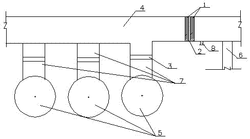
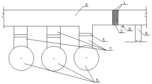
[0011] The method of gas isolation in the hot blast furnace of this ironworks has been successfully applied in the 1# and 2# 1780 m3 blast furnace projects of Jiujiang Steel Works and the 1080 m3 blast furnace project of Jiujiang Steel Works; the 1# and 2# 1780 m3 blast furnace projects of Jiujiang Steel Works The inner diameter of the hot air main pipe is 2368 mm, and the thickness of the left and right partition walls is 232 mm. The heat insulation layer between the left and right partition walls is a ceramic fiber blanket with a thickness of 10 mm. mm, the construction period was shortened by 25 days, and the cost was reduced by 330,000 yuan; the inner diameter of the hot blast main pipe of the 1080 m3 blast furnace project in Jiujiang Steel Plant was 2368 mm, and the thickness of the left and right partition walls was 232mm. The heat insulation layer between the left and right partition walls was ceramic fiber blanket. The thickness of the thermal layer is 10 mm, the refrac...


PUM


Abstract

The present invention relates to a gas isolation method used during the drying of a hot-blast stove in an iron works, and belongs to the construction method of a hot-blast stove. The method is characterized in that a left and a right high-alumina brick partition walls are arranged near a wind-mixing pipe by corresponding to the left part of a manhole in the inner cavity of a hot-blast main; high-alumina bricks are pre-placed before the left and the right partition walls are made; lines are drawn on arc bricks, and then the arc bricks are finish-machined and numbered; a stove builder makes thewalls layer by layer from the bottom and fills the joints layer by layer, near a right hot-blast branch pipe in the hot-blast main; when the left and the right partitions are made 700mm from the top,the stove builder moves across the left and the right partitions to one side of the wind-mixing pipe to finish making the rest of the walls; the mortar plumpness is up to 95%; the size of mortar joints is 2 mm plus or minus 1mm; the thicknesses of the left and the right partition walls range from 230 to 250mm on average; refractory layers are applied to the outer surfaces of the left and the right partition walls; and the thickness of the refractory layers can range from 2 to 3mm. The method can effectively isolate gas. The hot-blast pipe and a blast furnace are made simultaneously, which guarantees the schedule.

Description

technical field [0001] The invention belongs to a construction method of a hot blast stove, in particular to a gas isolation method of a hot blast stove. Background technique [0002] At present, during the construction of the ironworks, the hot blast stove is baked simultaneously with the hot blast pipeline and the blast furnace masonry. The method of isolating the gas to prevent leakage is to realize the gas isolation by setting a steel blind plate at the flange of the hot blast valve. The steel blind plate , Aluminum gaskets and connecting bolts are combined to form a gas isolation device for the oven. After the gas alarm test confirms that there is no gas leakage, the gas isolation device is effective. The disadvantages of this device are: when removing the steel blind plate, it is necessary to It will cause great damage to the refractory fiber blanket in the expansion joint at the hot blast valve, and it will take a long time to install and dismantle it. After the blast...

Claims


Application Information

Patent Timeline
IPC IPC(8): C21B9/10
Inventor 赵家贵刘守城
Owner CHINA MCC17 GRP
Learn More