Rotary drilling rig and control mode thereof

A technology of a rotary drilling rig and a control method, which is applied in directions such as rotary drilling rigs, drilling equipment and methods, and automatic control systems for drilling, can solve problems such as equipment wear and low efficiency of drilling rod locking.

Inactive Publication Date: 2012-03-28
SHANGHAI ZOOMLION HEAVY IND PILING MACHINERYCO +1
View PDF6 Cites 26 Cited by
  • Summary
  • Abstract
  • Description
  • Claims
  • Application Information

AI Technical Summary

Problems solved by technology

[0004] The present invention aims to provide a rotary drilling rig and its control method to solve the problems of low drilling rod locking efficiency and serious equipment wear in the prior art

Method used


Image

  • Rotary drilling rig and control mode thereof
  • Rotary drilling rig and control mode thereof
  • Rotary drilling rig and control mode thereof

Examples


Embodiment Construction

[0021] It should be noted that, in the case of no conflict, the embodiments in the present application and the features in the embodiments can be combined with each other. The present invention will be described in detail below with reference to the accompanying drawings and examples.

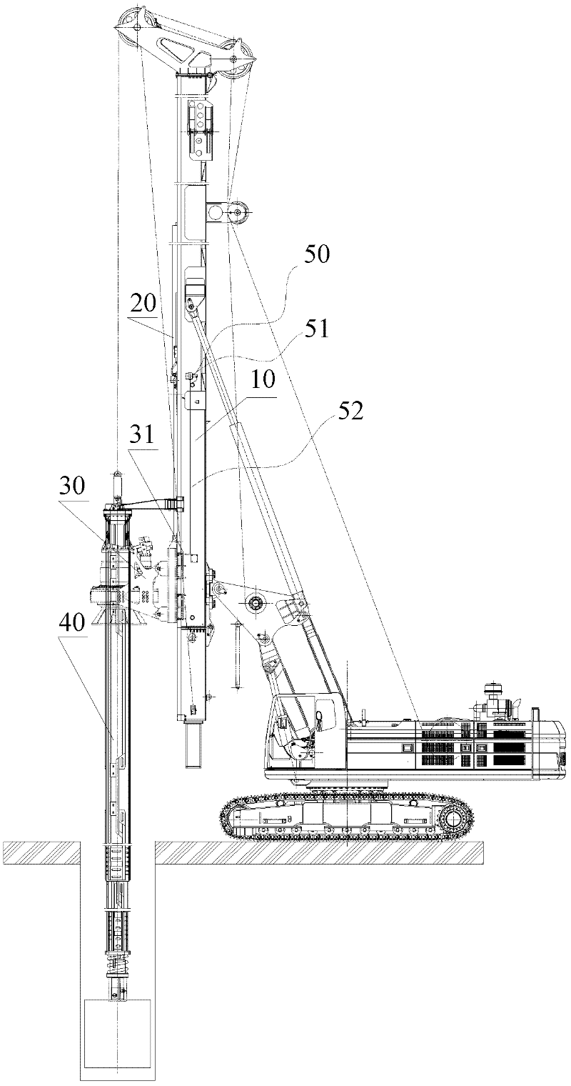
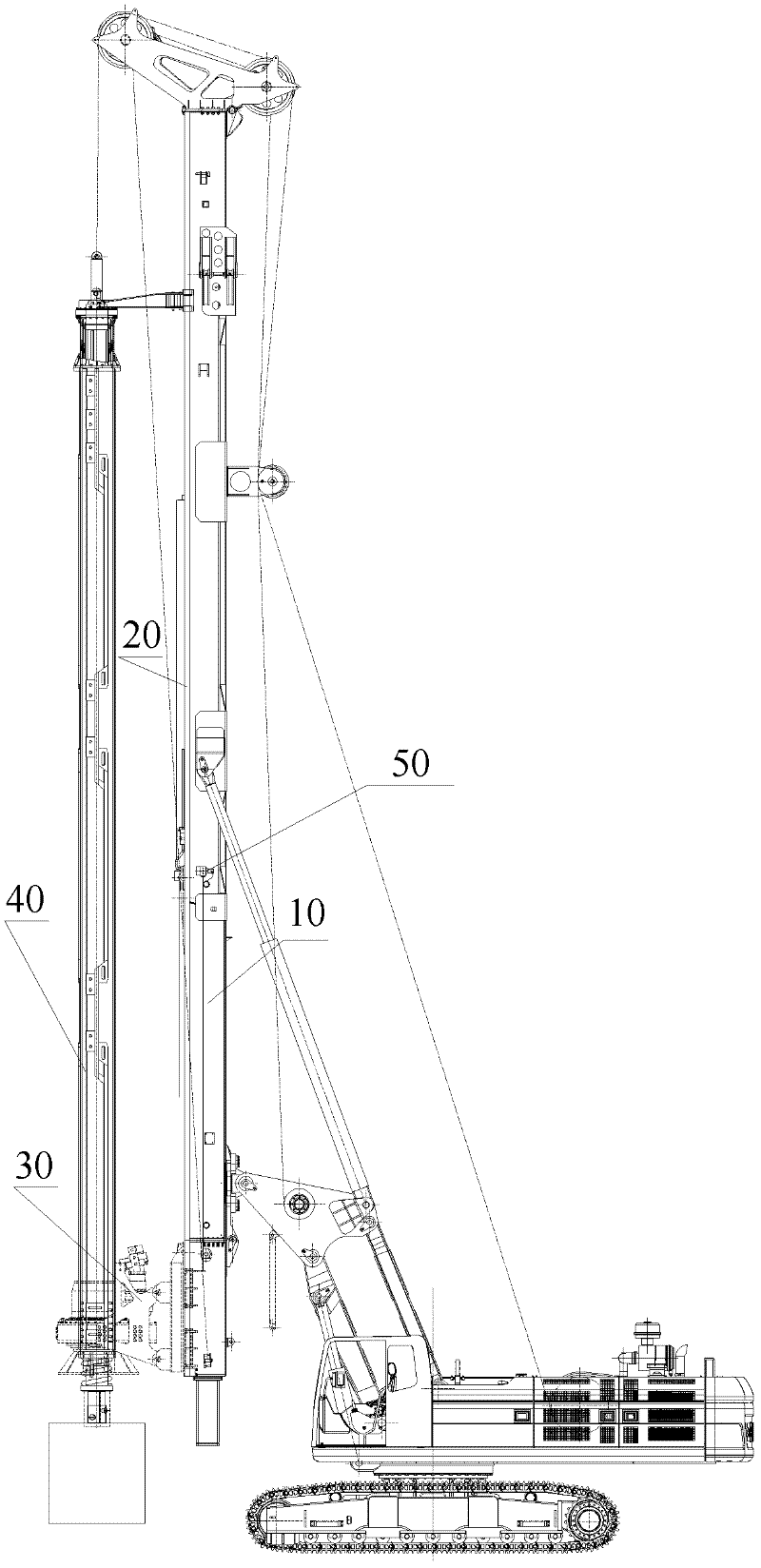
[0022] figure 1 A schematic view showing the working state of an embodiment of the rotary drilling rig according to the present invention; figure 2 It shows the schematic diagram of the unloading state of the embodiment of the rotary drilling rig according to the present invention. see in conjunction Figure 1 to Figure 2 , As can be seen from the figure, the rotary drilling rig of this embodiment includes: a mast 10, a pressurized cylinder 20, a power head 30, a drill pipe assembly 40, a main winch, a distance measuring device 50 and a controller.

[0023] The mast 10 is the supporting part of the drill pipe assembly 40. It is subjected to torque, vibration, etc. during work, and the worki...


PUM


Abstract

The invention provides a rotary drilling rig comprising a mast (10), a pressurizing oil cylinder (20), a power head (30), a drill rod assembly (40), a distance-measuring device (50) and a controller, wherein the mast (10) is arranged along the vertical direction; the pressurizing oil cylinder (20) is arranged on the mast (10), the piston rod of the pressurizing oil cylinder (20) is arranged downward; the power head (30) is connected with the piston rod of the pressurizing oil cylinder (20); the drill rod assembly (40) is in drive fit with the power head (30) and is provided with a machine-locked type drill rod; the distance-measuring device (50) is used for measuring the moving distance of the power head (30); and the controller is connected with the distance-measuring device (50), determines the current position of the power head (30), compares the current position with an unblocking position where the power head (30) is when the drill rod assembly (40) is unblocked, and sends a control signal to the pressurizing oil cylinder (20) according to the comparative result. The invention effectively solves the problems in the prior art that the drill rod locking efficiency is low, and the equipment wear is serious.

Description

technical field [0001] The present invention relates to engineering machinery, in particular to a rotary drilling machine and a control method thereof. Background technique [0002] In the rotary drilling rigs in the prior art, the lock of the machine-locked drill pipe is locked by the judgment of the operator. This process is: the drill pipe is unlocked first. position (that is, the unlocked position), and then lift the main winch, so that the drilling tool is out of the hole, and then rotate the upper car body to realize soil unloading or other operations. When unloading soil or other operations, the position of the power head needs to be moved. Before the next drilling, the operator needs to park the power head at the previously remembered position (unlock position), and then lower the drill pipe to the end and try to get it. Lock in, and then realize the pressurized drilling of the drill pipe. [0003] In the above process, the unlocking position of the power head is d...

Claims


Application Information

Patent Timeline
Patent Type & Authority Applications(China)
IPC IPC(8): E21B44/02E21B3/02
Inventor 孙涛李超周靖杨涛王亚伟
Owner SHANGHAI ZOOMLION HEAVY IND PILING MACHINERYCO
Why Eureka
Try Eureka