Axial magnetic bearing

A technology of axial magnetic bearings and permanent magnets, applied in the field of axial magnetic bearings, can solve the problems that the rotor can only be controlled by axial translation, cannot be controlled by the radial torsion of the rotor, and the axial length increases, etc., and achieve power consumption Low, the effect of reducing the axial length and reducing the rotation loss

Inactive Publication Date: 2012-03-28
NORTH CHINA UNIVERSITY OF TECHNOLOGY
View PDF5 Cites 12 Cited by
  • Summary
  • Abstract
  • Description
  • Claims
  • Application Information

AI Technical Summary

Problems solved by technology

The axial magnetic bearing stator structure of most existing structures is a full circle structure, which can only control the axial translation of the rotor, but cannot control the radial torsion of the rotor. Therefore, in applications where the overall axial length of the system is required to be small It is difficult to be applied in some occasions, especially the existing flywheel system, which is usually made into an outer rotor structure to reduce the overall volume, and the radial magnetic bearings used in pa

Method used


Image

  • Axial magnetic bearing
  • Axial magnetic bearing
  • Axial magnetic bearing

Examples


Embodiment Construction

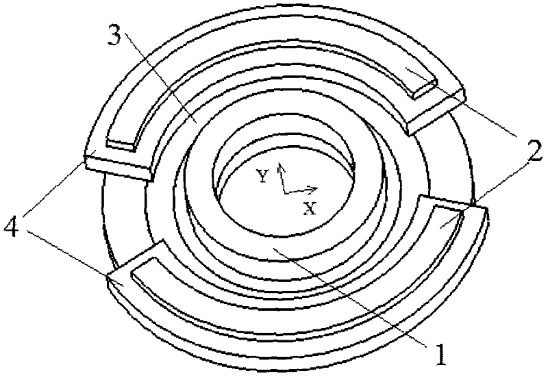
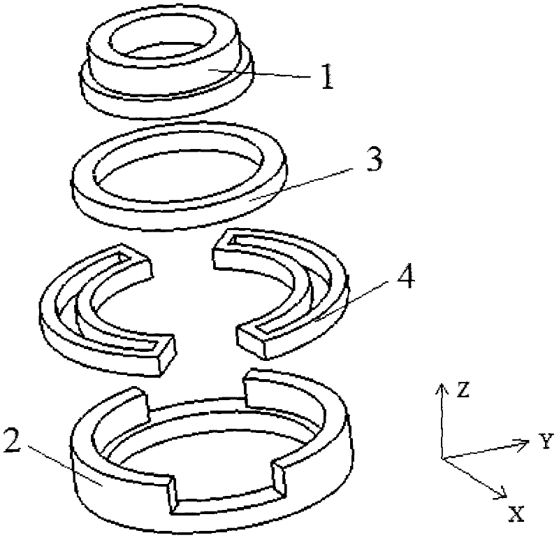
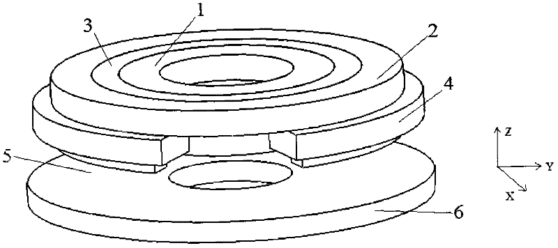
[0014] Such as figure 1 , figure 2 with image 3 As shown, the axial magnetic bearing with controllable radial torsion of the present invention is composed of a stator part and a rotor 6, and the stator part is composed of an inner ring stator core 1, an outer ring stator core 2, a permanent magnet 3 and a coil 4, wherein The inner ring stator core 1 is a complete ring structure, and the outer ring stator core 2 has two stator core poles, which are placed along the +Y, -Y direction or +X, -X direction, and each stator core pole is wound with a coil 4 , Axial magnetic air gap 5 is formed between inner stator core 1, outer stator core 2 and rotor 6, radial inner side of permanent magnet 3 is connected with inner ring stator core 1, and radial outer side is connected with outer ring stator core 2. from figure 2 It can be seen that the relative positional relationship between the various parts of the axial magnetic bearing stator (inner ring stator core, outer ring stator cor...


PUM


Abstract

The invention provides an axial magnetic bearing, and particularly relates to the axial magnetic bearing of which the radial torsion can be controlled. The axial magnetic bearing comprises a stator part and a rotor, wherein the stator part comprises an inner-ring stator core, an outer-ring stator core, a permanent magnet and coils; the inner-ring stator core adopts an integral ring structure; the outer-ring stator core comprises two stator core magnetic poles which are arranged in the +X direction and the -X direction (or the +Y direction and the -Y direction); the coils are wound on the stator core magnetic poles respectively; an axial magnetic airgap is formed between the stator part and the rotor; the radial inner side of the permanent magnet is connected with the inner-ring stator core; and the radial outer side of the permanent magnet is connected with the outer-ring stator core. The axial magnetic bearings provided by the invention are required to be used in pairs, so that the radial torsion of the rotors can be controlled when the outer-ring magnetic poles of two axial magnetic bearings are placed in different positions, which greatly reduces the axial size of the system. The axial magnetic bearing further has the advantages of low rotation loss, reliable performance, convenience in control, and the like.

Description

technical field [0001] The invention relates to a non-contact magnetic suspension bearing, in particular to an axial magnetic bearing capable of controlling radial torsion, which can be used as a non-contact support for rotating parts in spacecraft such as small satellites. Background technique [0002] Commonly used magnetic suspension bearings are divided into electromagnetic bias type and permanent magnetic bias plus electromagnetic control hybrid magnetic suspension bearing. The former uses current to generate a bias magnetic field, so the working current is large and the power consumption is large. The latter uses permanent magnets instead of current to generate a bias magnetic field. , The magnetic field generated by the permanent magnet bears the main bearing capacity, and the electromagnetic field provides the auxiliary adjustment bearing capacity, so this kind of bearing can greatly reduce the control current and reduce the loss. The axial magnetic bearing stator st...

Claims


Application Information

Patent Timeline
IPC IPC(8): F16C32/04
Inventor 贾新涛
Owner NORTH CHINA UNIVERSITY OF TECHNOLOGY
Why Eureka
Try Eureka