End screen differential digital output transformer

A digital output, transformer technology, applied in the direction of inductors, transformers/inductor coils/windings/connections, transformers, etc., can solve the problem that the capacitance of the low-voltage arm C2 of the output voltage of the capacitor voltage divider is not large enough, insulation failure faults, capacitance The problem of high output voltage of the voltage divider can achieve the effect of isolating primary equipment and measurement and control equipment, protecting measuring and measuring instruments, and ensuring the accuracy of current conversion

Active Publication Date: 2012-03-28
BEIJING SIFANG JIBAO AUTOMATION +1
View PDF5 Cites 8 Cited by
  • Summary
  • Abstract
  • Description
  • Claims
  • Application Information

AI Technical Summary

Problems solved by technology

[0008] 1. The output voltage of the capacitive voltage divider is too high, even reaching hundreds of volts. On the one hand, it cannot be directly connected to conventional electronic circuits (the conventional input voltage is generally about 3V), on the other hand, it is easy to be connected near the end screen and the lead-out wires. Insulation failure along the way
The reason why the output voltage of the capacitive voltage divider is too high is that the capacitance of the low-voltage arm C2 is not large enough, which is caused by the limitation of structure and process, because C2 is composed of the last screen and the previous screen, and the insulation thickness between the two screens is as follows: The current material and technology level can only be the thinnest 50-100μm, so the value of C2 is limited, and the voltage shared by it is relatively high
After calculation, for a 110kV transformer, in order to obtain an output voltage of about 3V, the insulation thickness between the last screen and the previous screen should be reduced to about 2μm, which is not yet possible
[0009] 2. The secondary output of the utility model 99255044.0 scheme is an analog quantity, which cannot be directly used as an input signal for digital measuring instruments and relay protection devices
[0010] 3. In the scheme of invention patent 200410086285.1, the secondary coil of the current transformer is a Rogowski coil. Although this coil has the advantages of low cost and wide linear range, it does not have an iron core to concentrate the magnetic field, so it is used from The accuracy of the signal coupled from the primary winding will be affected by changes in the installation location and environmental conditions (such as temperature, humidity), etc., and finally reflected in the large error of the transformer, especially for the transformer used for electricity metering, it is difficult to meet the requirements

Method used


Image

  • End screen differential digital output transformer
  • End screen differential digital output transformer
  • End screen differential digital output transformer

Examples


Embodiment Construction

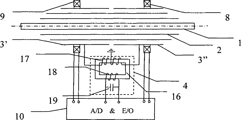
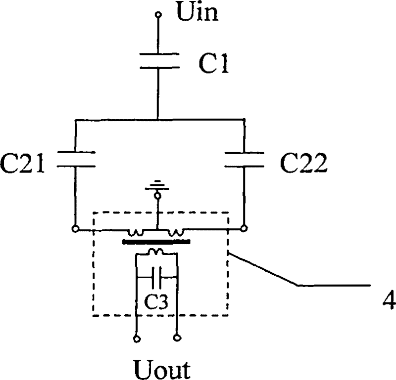
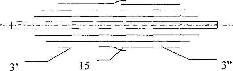
[0028] see figure 1 , the final screen differential digital output transformer of the present invention includes a high-voltage electrode (0 screen) 1, an intermediate capacitive screen 2, a final screen 3' and 3 "divided into two sections, a differential converter 4, an ultramicrocrystalline iron core coil 8, and silicon steel Sheet iron core coil 9, and integrated terminal 10. High-voltage electrode 1 is wrapped with insulating material, and intermediate capacitive screen 2 is laid at an appropriate position during the winding process. There can be multiple intermediate capacitive screens 2; the last capacitive screen (ie, the last screen) Divide it into two sections of 3' and 3" with different lengths, and tie the lead wires on 3' and 3" respectively, so that the capacitive primary winding of the final screen differential is completed. After laying two sections of the final screen 3' and 3", attention should be paid to the insulation between them, a feasible solution such a...


PUM


Abstract

The invention relates to an end screen differential digital output transformer, belonging to the field of high-voltage apparatuses. The end screen differential digital output transformer comprises a U-shaped or straight line-shaped capacitive-type primary winding, an ultracrystalline iron core coil, a silicon steel sheet iron core coil, a differential converter, an integrated terminal and the like. The end screen of the capacitive-type primary winding is divided into two segments with different lengths; two unequal capacitive currents extracted from the two segments are grounded through the input terminal of the differential converter; the output terminal of the differential converter obtains a low-voltage signal proportional to a primary voltage; the ultracrystalline iron core coil and the silicon steel sheet iron core coil can induce a low-voltage signal proportional to a primary current; and the integrated terminal converts the analog electrical signals into digital optical signals, and respectively provides the digital optical signals to a digital measurement instrument and a microcomputer protection device. The end screen differential digital output transformer has the functions of a voltage transformer and a current transformer, and the intermediate low-voltage analog signals are in a weak current range, so that the end screen differential digital output transformer is safe and reliable and has the advantages of high resistance to common mode interference, small error and high accuracy.

Description

technical field [0001] The invention belongs to the field of high-voltage electrical appliances, and is used in power plants, substations and other places to convert primary voltage and current into secondary voltage and current, and digitally provide signals to digital measuring instruments or relay protection devices. Background technique [0002] The existing high-voltage transformers are mainly electromagnetic and photoelectric, most of which are traditional electromagnetic, and the number of photoelectric is very small, which is an emerging technology in recent years. In addition, there are literatures that introduce other transformer schemes that combine the characteristics of the electromagnetic type and the photoelectric type (referred to as combined electronic transformers in this specification). [0003] The traditional electromagnetic voltage transformer uses the principle of electromagnetic induction to convert the primary high voltage (above tens of kilovolts) i...

Claims


Application Information

Patent Timeline
Patent Type & Authority Applications(China)
IPC IPC(8): H01F38/34H01F27/28H01F27/32G01R15/18
Inventor 李培国
Owner BEIJING SIFANG JIBAO AUTOMATION
Why Eureka
Try Eureka