Millimeter-wave wideband TE01-mode rotating joint

A rotary joint and millimeter wave technology, applied in the field of communication, can solve the problems of efficient transmission of unfavorable signals, no detail, no TE01 mode rotary joint, etc., and achieve the effects of high-efficiency transmission performance, short design cycle, and compact structure

Inactive Publication Date: 2014-04-23
INST OF ELECTRONICS ENG CHINA ACAD OF ENG PHYSICS
View PDF5 Cites 0 Cited by
  • Summary
  • Abstract
  • Description
  • Claims
  • Application Information

AI Technical Summary

Problems solved by technology

However, the transmission loss of the main mode waveguide in the millimeter wave frequency band continues to increase, which is not conducive to the efficient transmission of signals, such as TE 01 The advantages of low transmission loss of high-order modes are revealed, so more and more millimeter-wave systems begin to use over-mode waveguides to propagate high-order modes to reduce transmission losses and improve signal transmission efficiency
Judging from the public literature at present, there is no information about TE in China. 01 There are no detailed literature introductions abroad on the report of modular rotary joints

Method used


Image

  • Millimeter-wave wideband TE01-mode rotating joint
  • Millimeter-wave wideband TE01-mode rotating joint

Examples


Embodiment Construction

[0016] The present invention will be further described in detail below in conjunction with the embodiments and the drawings, but the implementation method and the scope of protection of the present invention are not limited to this.

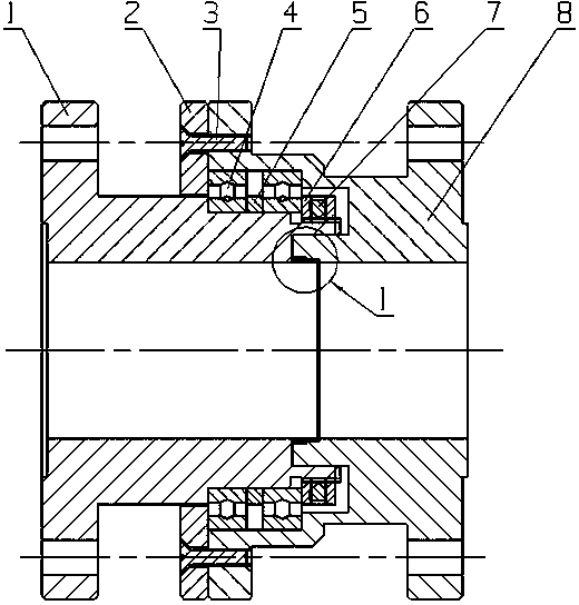
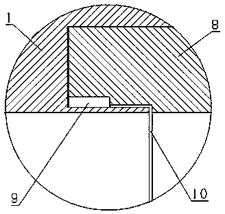
[0017] Such as figure 1 Shown, a millimeter wave broadband TE 01 The mode rotary joint is used to connect the rotary circular waveguide 1 and the fixed circular waveguide 8 and includes a fixed connection part and a rotation part. The rotary joint is a rotationally symmetric structure as a whole; the fixed connection part includes a fixed connection plate 2, a connection screw 3, and a connection screw 3 Connect and fix the rotating circular waveguide 1 and the fixed circular waveguide 8 through the fixed connecting plate 2. A cavity is left between the fixed connecting plate 2 and the rotating circular waveguide 1 and the fixed circular waveguide 8; the rotating part is set in the cavity , The main body is a deep groove ball rolling bearing 4 sleeve...


PUM


Abstract

The invention relates to a rotating joint technology in the field of communication, and in particular discloses a millimeter-wave wideband TE01-mode rotating joint. The rotating joint is used for connecting a rotary circular waveguide with a fixed circular waveguide and comprises fixedly connecting parts and rotating parts; the entire rotating joint is of a rotational symmetric structure; each fixedly connecting part comprises a fixedly connecting plate and a connecting screw; each connecting screw penetrates through the corresponding fixedly connecting plate to be fixedly connected with the corresponding fixed circular waveguide; hollow cavities are respectively retained between the connecting plates and the rotary circular waveguides and between the connecting plates and the fixed circular waveguides; the rotating parts are arranged in the hollow cavities; the main body of each rotating part is a deep-grooved-ball rolling bearing sleeved on the outer wall of the corresponding rotary circular waveguide; and the outer wall of each deep-grooved-ball rolling bearing is tightly attached to the inner wall of the corresponding fixed circular waveguide. In the invention, the wideband, low-loss and high-efficiency transmission of a millimeter-wave over-mode signal can be realized; and the rotating joint has the advantages of being short in design cycle, compact in structure, low in cost, easy to process, convenient to install, etc.

Description

Technical field [0001] The invention relates to a rotary joint technology in the communication field, in particular to a millimeter wave broadband TE 01 Mold rotation joints. Background technique [0002] In the application of modern radar systems and communication systems, in order to search for targets, track targets, and measure the spatial position of targets, the antenna of the system must be rotated at any time. Rotary joints are just to meet the needs of antennas to continuously search for targets, track targets and measure targets during work, and are an important device for completing the task of microwave signal transmission when the antenna is rotating. For example, the publication date is 2010.07.21, and the publication number is CN 201532999U. The Chinese patent document discloses a straight-through radio frequency coaxial rotary joint, which includes a coaxially arranged rotating part and a fixed part; wherein, a core rod, an insulating bush, The connecting sleeve,...

Claims


Application Information

Patent Timeline
Patent Type & Authority Patents(China)
IPC IPC(8): H01P1/06
Inventor 陈琦李相森赫英毅唐先发杨春崔奉云李林翠任冬梅
Owner INST OF ELECTRONICS ENG CHINA ACAD OF ENG PHYSICS
Why Eureka
Try Eureka