Fault recovery method of wireless sensor network

A wireless sensor, fault recovery technology, applied in network topology, wireless communication, network data management and other directions, can solve the problems of lost fault recovery, long recovery time, long fault recovery time, etc., to shorten the distance of node movement, optimize Recovery process, effect of prolonging the life cycle

Inactive Publication Date: 2012-03-28
BEIJING UNIV OF POSTS & TELECOMM
View PDF3 Cites 5 Cited by
  • Summary
  • Abstract
  • Description
  • Claims
  • Application Information

AI Technical Summary

Problems solved by technology

If multiple nodes fail at the same time, it will cause server information congestion
Moreover, when multiple nodes fail, the communication quality on the path from the faulty node to the server cannot be guaranteed, which will cause the server to make a wrong decision.
[0009] (2) The transposition node moves too far, consumes too much energy, and takes too long to recover
[0010] (3) The existing fault recovery technology algorithm is relatively complicated
Both the method and the DORMS algorithm disclosed in the Chinese invention patent application with the publication number CN102111789A need to be optimized, and the recovery process is relatively complicated
In the case of a relatively large scale of actual network nodes, the time for fault recovery is relatively long, and the meaning of fault recovery has been lost

Method used


Image

  • Fault recovery method of wireless sensor network
  • Fault recovery method of wireless sensor network
  • Fault recovery method of wireless sensor network

Examples


Embodiment Construction

[0049] A fault recovery method for a wireless sensor network proposed by the present invention will be described in detail below with reference to the drawings and embodiments.

[0050] First of all, it should be noted that the abbreviation as "node" in the following content refers to transposed nodes.

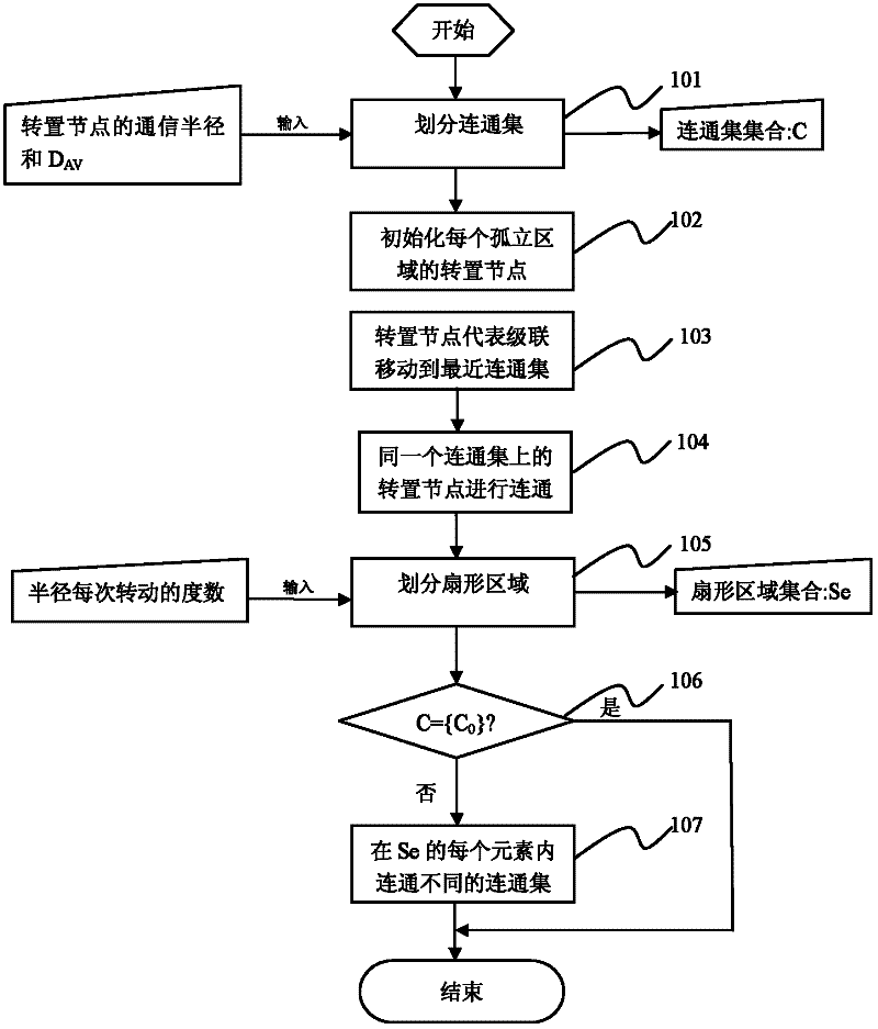
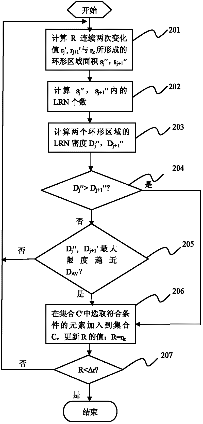
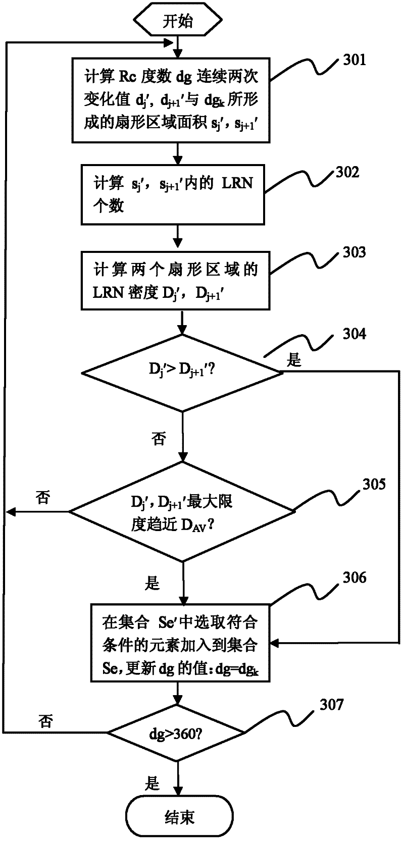
[0051] Refer below Figure 1 ~ Figure 3 Introduce each step separately:

[0052] 101) Divide connected sets (Connected Set, CS). In order to move the transposed nodes of each isolated region to the CS closest to itself, the positions of these CSs need to be determined according to the distribution density of the nodes. In the present invention, CS is defined as a concentric circle with the geometric center point of the network monitoring area as the center, so determining the position of CS is to determine the radius value R of the concentric circle, wherein the initial value of R is the largest concentric circle (i.e. the farthest isolated The circle where the area is loca...


PUM


Abstract

The invention relates to the wireless sensor network technology field and discloses a fault recovery method of a wireless sensor network. In the invention, through a leading relay node (LRN), an isolated area which loses connection is reconnected to a nearest connected set (CS), and then the CSs are connected so as to realize a purpose of recovering network connectivity. Because the LRN in the each isolated area only needs to move to the CS which is nearest to the LRN itself, a shift distance can be substantially shortened and node energy can be saved too. In the invention, according to a density of the LRN, CS division is performed to the whole network and simultaneously, during a connection process of the different CSs, a density approach method is still used to perform the fan-shaped division so that an LRN optimization process between the isolated areas can be simplified and complexity of algorithm can be reduced.

Description

technical field [0001] The invention relates to the technical field of wireless sensor networks, in particular to a fault recovery method for wireless sensor networks. Background technique [0002] The fault recovery technology of the current wireless sensor network is mainly based on the fault recovery technology of a single node (referring to the sensor node) and the fault recovery technology based on the block area. The failure recovery technology based on a single node considers that only a single sensor node fails at the same time. The fault recovery technology based on block area refers to the strategy adopted when multiple nodes fail at the same time. [0003] The fault recovery technology based on a single node mainly uses neighbor nodes to replace the faulty node, and takes measures on the faulty node itself. [0004] The Chinese invention patent application with the publication number CN102111789A uses redundant nodes to replace failed nodes. The method includes...

Claims


Application Information

Patent Timeline
Patent Type & Authority Applications(China)
IPC IPC(8): H04W8/30H04W24/04H04W84/18
CPCY02B60/50Y02D30/70
Inventor 亓峰邱雪松高娟詹志强王颖熊翱王智立
Owner BEIJING UNIV OF POSTS & TELECOMM
Why Eureka
Try Eureka