Optical sensors that reduce specular reflections

An optical sensing and photodetector technology, applied in the field of optical sensors, can solve the problem that optical sensors are easily affected by mirror reflection, and achieve the effects of simple cost-effectiveness, reduced sensitivity and low cost

Inactive Publication Date: 2012-03-28
INTERSIL INC
View PDF7 Cites 29 Cited by
  • Summary
  • Abstract
  • Description
  • Claims
  • Application Information

AI Technical Summary

Problems solved by technology

When such a cover is placed over an optical sensor, the o

Method used


Image

  • Optical sensors that reduce specular reflections
  • Optical sensors that reduce specular reflections
  • Optical sensors that reduce specular reflections

Examples


Embodiment Construction

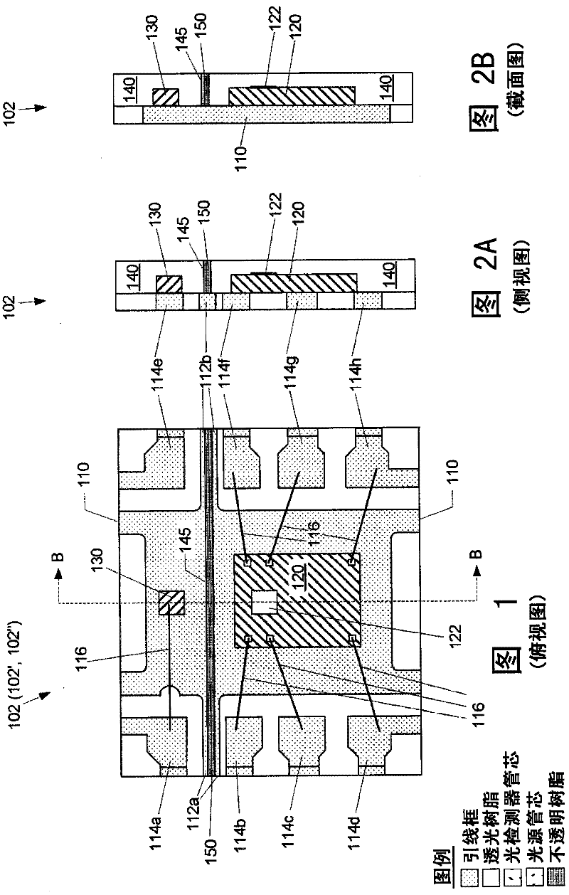
[0054] figure 1 It is a top view of an optical sensing device 102 (such as a proximity sensing device) according to a specific embodiment of the present invention. According to the first embodiment of the present invention, Figure 2A Yes figure 1 Side view of the device 102, and Figure 2B Yes figure 1 with Figure 2A Sectional view of device 102 (along figure 1 Dashed line B-B).

[0055] Such as figure 1 As shown, the optical sensing device 102 includes a die attach substrate 110, although in figure 1 It is shown as a die-attached lead frame substrate, but a circuit board substrate or a ceramic substrate can be additionally selected, but it is not limited thereto. The benefit of using one or more lead frames as the die attach substrate is that the lead frame substrate can typically be made thinner than the circuit board substrate or ceramic substrate, which can reduce the thickness of the entire device 102, depending on the device 102 used. The use of may be desirable. For exa...


PUM


Abstract

An optical sensor device, according to an embodiment of the present invention, includes a light source and a light detector. The light source includes one or more light emitting elements, and the light detector includes one or more light detecting elements. A first opaque light barrier portion, between the light source and the light detector, is configured to block light from being transmitted directly from the light source to the light detector. A second opaque light barrier portion, extending from the first opaque light barrier portion in a direction towards the light source, is configured to reduce an amount of specular reflections that would occur if a light transmissive cover plate were placed over the optical sensor device.; A third opaque light barrier portion, extending from the first light barrier portion in a direction towards to the light detector, is configured to reduce an amount of specular reflections that would be detected by the light detector, if a light transmissive cover plate were placed over the optical sensor device.

Description

[0001] Priority statement [0002] This application claims the priority of the following U.S. patent applications: [0003] ●U.S. Provisional Patent Application No. 61 / 169,236, entitled "OPTICAL SENSORS AND METHODS FOR PROVIDING OPTICAL SENSORS" (OPTICAL SENSORS AND METHODS FOR PROVIDING OPTICAL SENSORS), granted to Lynn K. Wiese et al., submission date: April 2009 14th (the agency file number: ELAN-01227US0); [0004] ●U.S. Provisional Patent Application No. 61 / 218,867, entitled "OPTICAL SENSORS THAT REDUCE SPECULAR REFLECTIONS", granted to Lynn K. Wiese et al., filing date: June 19, 2009 (Agency file No.: ELAN-01247US0); [0005] ●US Patent Application No. 12 / 499,693, entitled "OPTICAL SENSORS AND METHODS FOR PROVIDING OPTICAL SENSORS" (OPTICAL SENSORS AND METHODS FOR PROVIDING OPTICAL SENSORS), granted to Lynn K. Wiese et al., submission date: July 8, 2009 Date (the agency file number: ELAN-01227US1); [0006] ●US Patent Application No. 12 / 499,723, entitled "OPTICAL SENSORS THAT RE...

Claims


Application Information

Patent Timeline
IPC IPC(8): G01B11/00G01N21/27
CPCH01L2924/3011H01L31/0232H01L2224/49171H01L25/167H01L31/02325H01L31/173H01L2224/48247H01L2924/00G01B11/026G01B11/14
Inventor L·K·维斯N·凯尔科V·帕特沃德哈
Owner INTERSIL INC
Why Eureka
Try Eureka