
Novel squeeze roller type roller surface structure

A squeezing roller and a new type of technology, applied in the field of squeezing rollers, can solve the problems of unfavorable studs, single replacement of roller sleeves, sustainable use, increased equipment maintenance cycle and cost, damage or breakage, etc., to achieve performance improvement, abrasion resistance and other problems. Strong, long-life effect

Active Publication Date: 2012-04-04
CITIC HEAVY INDUSTRIES CO LTD +1
View PDF13 Cites 7 Cited by
  • Summary
  • Abstract
  • Description
  • Claims
  • Application Information

AI Technical Summary

Problems solved by technology

The outcropping of studs used in the stud roller surface structure of traditional high-pressure roller mills is higher than the roller surface. The stud at the head will cause damage or break fatal injury, and because the stud is set in the stud hole in the form of interference fit, it is difficult to pull out the stud when it is damaged or broken, which is not conducive to the separate replacement of the stud and the roller The sustainable use of the sleeve, even the entire roller sleeve has to be scrapped, which increases the cycle and cost of equipment maintenance

Method used


Image

  • Novel squeeze roller type roller surface structure
  • Novel squeeze roller type roller surface structure
  • Novel squeeze roller type roller surface structure

Examples


Embodiment 1

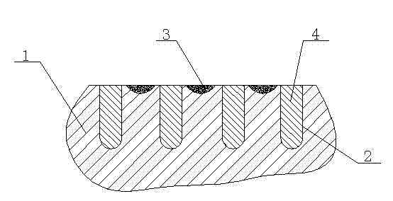
[0032] Such as figure 1 As shown, the roll surface structure: the outer surface of the roller sleeve 1 is provided with staggered column holes 2 and arc-shaped grooves 3, and the column holes 2 are provided with studs 4 that are flush with the surface of the roller sleeve 1. The nail 4 is arranged in the column hole 2 in the form of a clearance fit, and an adhesive is provided on the outer surface of the column nail and the inner surface of the column hole, and the high-strength adhesive combines the two firmly into one.

Embodiment 2

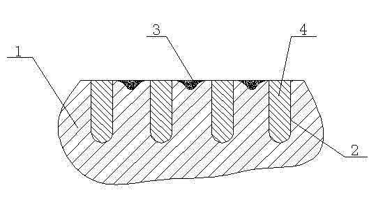
[0034] Such as figure 2 As shown, the roll surface structure: the outer surface of the roller sleeve 1 is provided with staggered column holes 2 and spherical grooves 3, the opening edge of the spherical groove and the surface of the roller sleeve are chamfered, and the column holes There is a stud 4 which is flush with the surface of the roller sleeve. The stud is arranged in the stud hole in the form of clearance fit, and an adhesive is provided on the outer surface of the stud and the inner surface of the stud hole. The high-strength adhesive binds the two firmly combined into one.

Embodiment 3

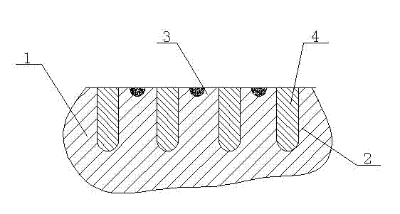
[0036] Such as image 3 As shown, the roll surface structure: the outer surface of the roller cover 1 is provided with staggered post holes 2 and hemispherical grooves 3, and the post holes are provided with studs 4 that are flush with the surface of the roll cover. The matching form is arranged in the column hole, and an adhesive is provided on the outer surface of the column nail and the inner surface of the column hole, and the high-strength adhesive combines the two firmly into one.


PUM

PropertyMeasurementUnit
Thicknessaaaaaaaaaa
Hardnessaaaaaaaaaa

Abstract

The invention discloses a novel squeeze roller type roller surface structure, which comprises a roller sleeve and stud nails, wherein stud holes and grooves are staggered and distributed on the outer surface of the roller sleeve; the stud nails are arranged in the stud holes by adhesive in a clearance fit mode; and the upper end surfaces of the stud nails are flush or lower than the outer surface of the roller sleeve. The squeeze roller type roller surface structure is characterized in that spherical pit or semi-spherical pit structures which are distributed on the whole roller surface and are staggered and arranged. When equipment is in load operation, one layer of self-generating material pad is generated on the surface of the roller sleeve. The material pad is used for bearing abrasion and impact by ultrahard objects, such as iron blocks and the like. The material pad of the structure has a high forming speed so as to improve the abrasion resistance of the roller surface, prolong the service life of the roller surface and improve the hard object impact resistance of the roller surface stud nails.

Description

[0001] technical field [0002] The invention relates to a squeeze roll for a high-pressure roller mill, especially a novel squeeze roll surface structure suitable for crushing / grinding various brittle materials in industrial fields such as building materials, metallurgy, mining, coal, and chemical industry. Background technique [0003] At present, high-pressure roller mills are mainly used in industrial fields such as building materials, metallurgy, mining, coal, and chemical industry. The two opposite-rotating extrusion rollers of the high-pressure roller mill generate huge extrusion force to crush the materials under the action of the hydraulic system. The roll surface life of squeeze rolls is related to equipment operation rate and maintenance cost. The outcropping of studs used in the stud roller surface structure of traditional high-pressure roller mills is higher than the roller surface. The stud at the head will cause damage or break fatal injury, and because the s...

Claims


Application Information

Patent Timeline
IPC IPC(8): B02C4/30
Inventor 王亚强祖大磊郝兵张光宇王素玲崔郎郎宋艾江王坷刚李聪杰张发展丁建华田鹤
Owner CITIC HEAVY INDUSTRIES CO LTD
Learn More