Impact torque adjusting device of hydraulic torque wrench

A torque wrench and torque adjustment technology, applied in the directions of wrenches, wrenches, screwdrivers, etc., can solve the problems of large impact torque impact torque error, applied load pressure on the sealing part, and long impact torque generation cycle, etc. Accuracy, the effect of reducing the travel stroke

Inactive Publication Date: 2012-04-04
URYU SEISAKU
View PDF10 Cites 7 Cited by
  • Summary
  • Abstract
  • Description
  • Claims
  • Application Information

AI Technical Summary

Problems solved by technology

[0009] (1) There is a large error between the actual impact torque and the set impact torque
[0010] (2) Abnormally high impact torque is likely to be generated when the tightening action starts (when the tightening parts are in place)
[0011] (3) After the impact torque is generated (after the pulse is generated), the resistance increases, and the generation cycle of the impact torque is long
[0012] (4) It is easy to apply load pressure to the sealing part, and the durability is not good
[0043] However, the impact torque adjusting device of the hydraulic torque wrench of the above-mentioned first to third reference examples is an impact torque adjusting device that achieves the above-mentioned excellent effect, but it can only rotate in one direction, specifically during forward rotation ( When tightening) it functions, and it rotates in the other direction, specifically, it does not function when it is reversed (when it is loosened), and the above-mentioned effects cannot be achieved

Method used


Image

  • Impact torque adjusting device of hydraulic torque wrench
  • Impact torque adjusting device of hydraulic torque wrench
  • Impact torque adjusting device of hydraulic torque wrench

Examples


Embodiment Construction

[0060] Next, an embodiment of an impact torque adjusting device for a hydraulic torque wrench according to the present invention will be described with reference to the drawings.

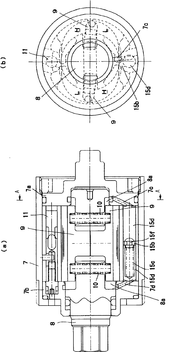
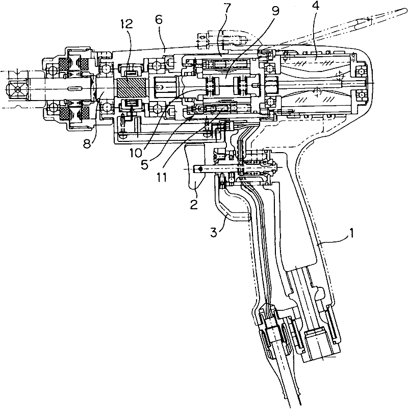
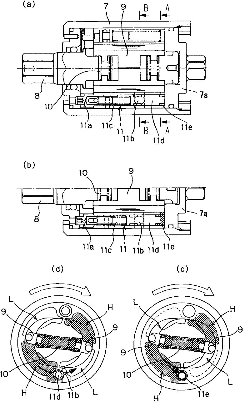
[0061] figure 1 It shows an embodiment of the impact torque adjusting device of the hydraulic torque wrench of the present invention (overall view omitted).

[0062] The hydraulic torque wrench 1 of the present embodiment controls the driving of the rotor 4 by the output of the torque detection mechanism such as the magnetostrictive torque detection mechanism 12 of the above-mentioned first reference example instead of the control of the drive of the rotor 4, and the above-mentioned second to second Three Reference Examples, Patent Document 1 and Figure 8 The disclosed conventional hydraulic torque wrench is similarly equipped with a release valve B in the output adjustment mechanism 11, and when the tightening action progresses, when the pressure (impact torque) of the working oil in the high pr...


PUM


Abstract

To present a impact torque adjusting device of a hydraulic torque wrench capable of enhancing the precision of the magnitude of the impact torque generated by the impact torque generating device of the hydraulic torque wrench, shortening the generation period of impact toques, and enhancing the durability of the impact torque generating device of the hydraulic torque wrench, when rotating in two directions, that is, in normal rotation (when tightening) and in reverse rotation (when loosening). The present invention provides a working fluid path (11b) for communicating with the inside of a liner (7) serving as a high-pressure chamber (H) and a low-pressure chamber (L) at the time of generation of a impact torque is formed, and a valve body (11d) biased in a direction of releasing the working fluid path (11b) is disposed in the working fluid chamber, and at the rear back side of the valve body (11d), an oil chamber (15e) is formed to communicate with a blade insertion part (8a) of a main shaft (8) by way of fluid paths (7c, 7d) formed in liner lids (7a, 7b), and thereby the working fluid path (11b) is narrowed depending on an elevation of the pressure of the working fluid in the blade insertion part (8a) of the main shaft (8) elevating along with an elevation of the working fluid in the high-pressure chamber (H).

Description

technical field [0001] The invention relates to an impact torque adjusting device of an oil hydraulic torque wrench. Background technique [0002] Conventionally, an impact torque generator as a torque wrench has been developed, and a hydraulic torque wrench using a hydraulic impact torque generator with low noise and vibration has been developed until it is put into practical use (for example, see Patent Documents 1 and 2). [0003] Figure 7 as well as Figure 8 It is a diagram showing an example of such a hydraulic torque wrench. The hydraulic torque wrench 1 has a main valve 2 for supplying and stopping high-pressure air, and a forward and reverse rotation switch for selectively generating an impact torque of forward and reverse rotation. The valve 3 drives the rotor 4 that generates the rotational torque through the high-pressure air fed through the two valves 2 and 3, and the oil that converts the rotational torque of the rotor 4 into an impact torque is installed in ...

Claims


Application Information

Patent Timeline
Patent Type & Authority Applications(China)
IPC IPC(8): B25B21/02
CPCB25B21/02B25B23/1453
Inventor 上村洋司
Owner URYU SEISAKU
Why Eureka
Try Eureka