Brake structure and wheelchair comprising same

A wheelchair and brake component technology, applied in the field of brake structure, can solve problems such as accidents, easy rushing down steep slopes, and very difficult problems, and achieve the effects of increasing safety and handling, preventing accidents, and increasing resistance

Active Publication Date: 2013-05-08
卫美恒(苏州)医疗器械有限公司
View PDF5 Cites 0 Cited by
  • Summary
  • Abstract
  • Description
  • Claims
  • Application Information

AI Technical Summary

Problems solved by technology

After the wheelchair in the prior art is braked, the rear wheel is fixed, and can neither move forward nor retreat, so it will cause difficulties for some weaker or slower users. For example, when encountering a steep slope, For users with insufficient strength, the uphill process will be very difficult. The user must quickly and continuously turn the rear wheel hand ring to make the wheelchair move forward so as not to walk backward; if the user wants to rest on the way uphill, It is necessary to lock the brake structure. When the rest is over, the wheelchair is easy to walk backward when the brake is turned on, and accidents occur; when going downhill, the brakes are usually not used, and the user only controls the rear wheel with both hands to control the downhill. Speed, if the user's strength is insufficient or improperly controlled, it is easy to rush down the steep slope and cause an accident

Method used


Image

  • Brake structure and wheelchair comprising same
  • Brake structure and wheelchair comprising same
  • Brake structure and wheelchair comprising same

Examples


Embodiment 1

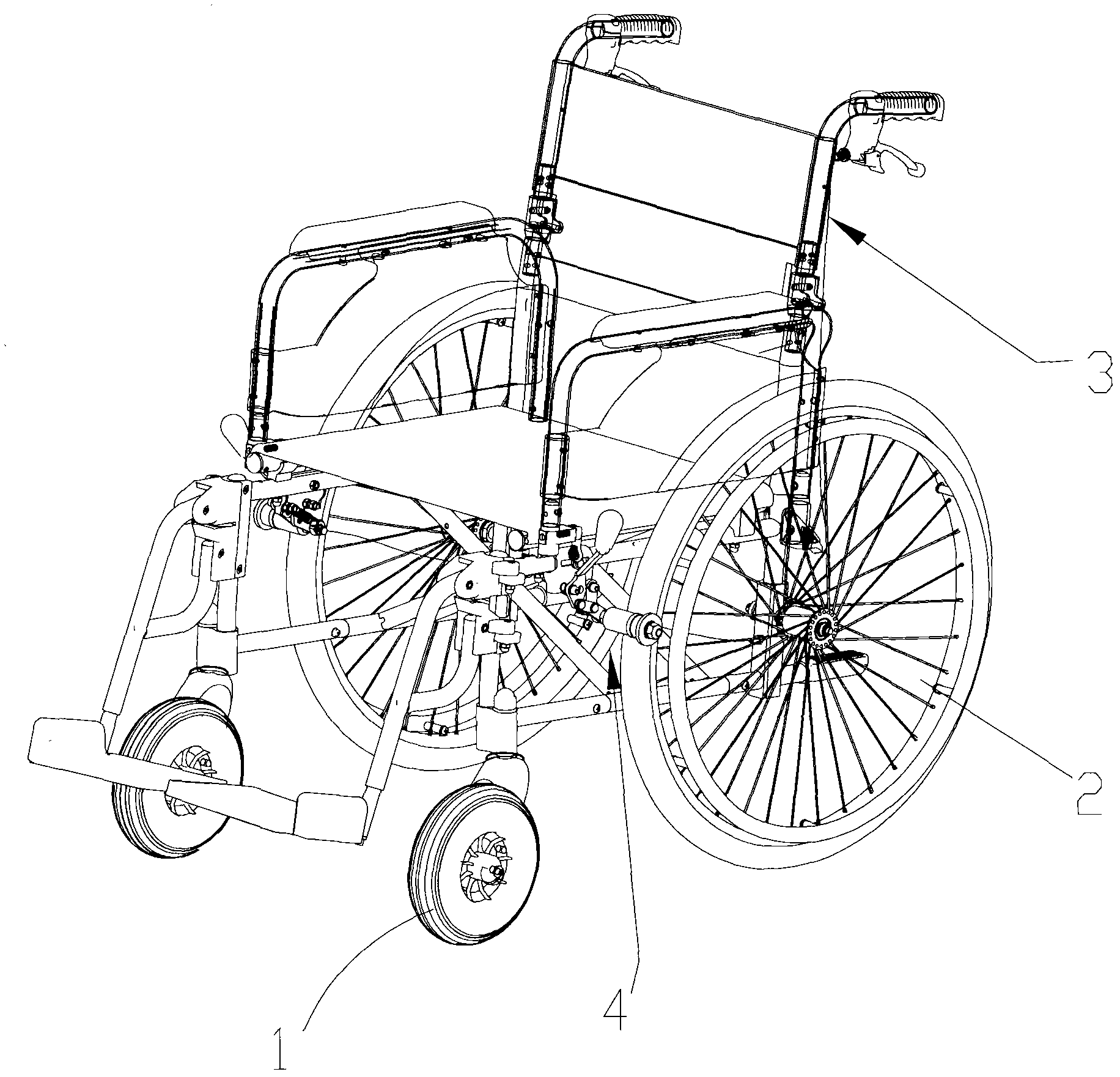
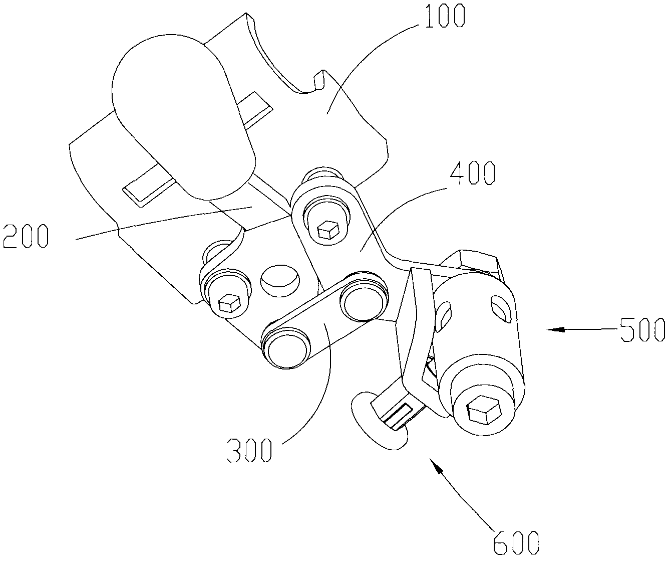
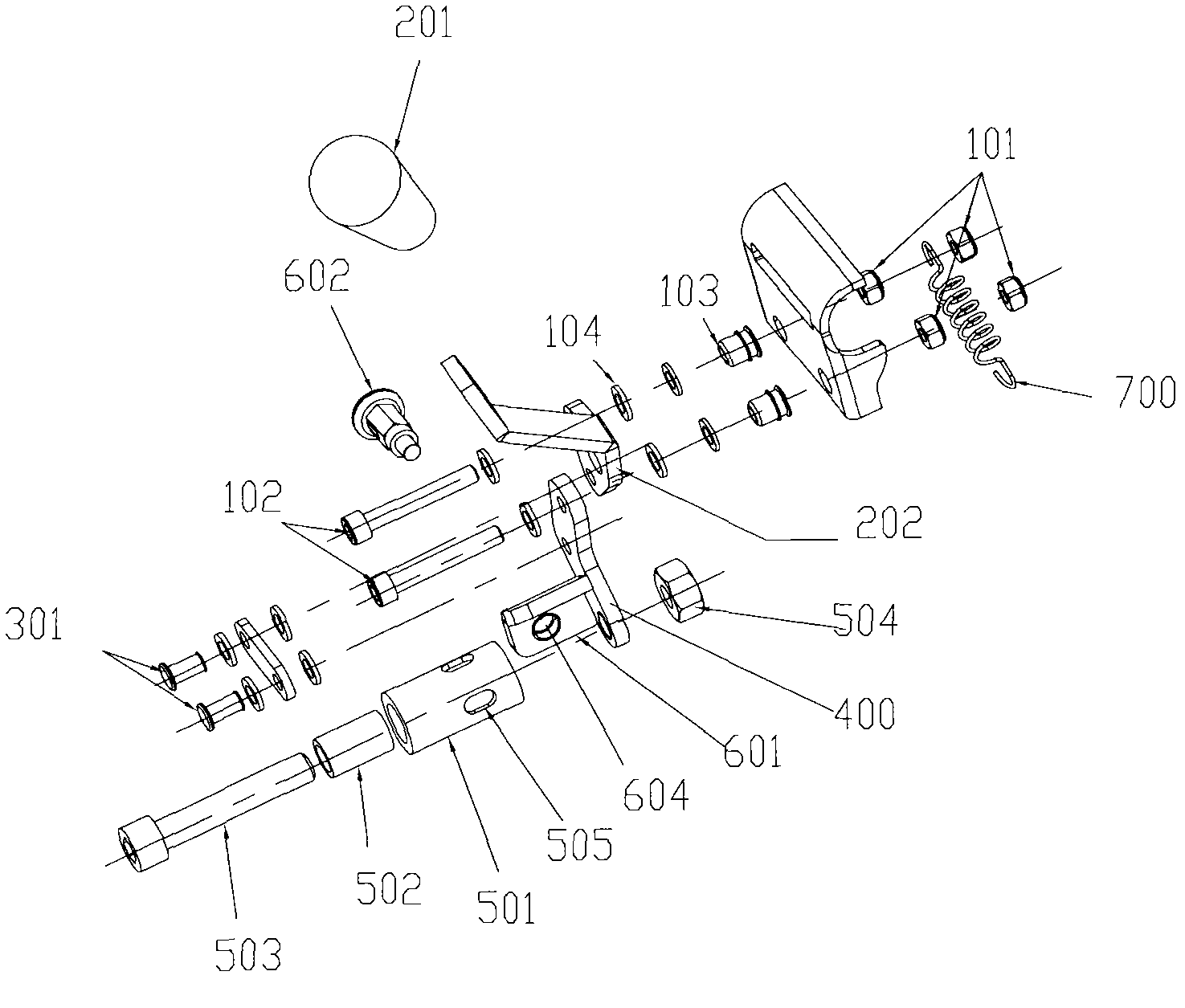
[0026] Embodiment 1: as figure 2 with image 3 As shown, the brake structure 4 mainly includes a mounting base plate 100 and a brake assembly 500 that is movably arranged on the mounting base plate 100 and is used to contact and rub the rear wheel of the wheelchair. The mounting base plate 100 is fixedly connected to the front part of the vehicle frame 3, And close to the rear wheel, so that the user can operate the brake. A handle 200 , a connecting rod 300 , a swing arm 400 , a locking mechanism 600 , a return spring 700 and the like are rotatably connected to the installation base 100 . The handle 200 includes a handle cover 201, a driving rod 202 and a mounting hole (not marked in the figure), etc., the handle 200 is connected to the mounting base plate 100 through a small screw rod 102 and a small nut 101 in rotation, and between the handle 200 and the mounting base plate 100 There is a spacer 104 and a sleeve member 103, the function of which is to make the handle 200...

Embodiment 2

[0030] Embodiment 2: The difference from Embodiment 1 lies in the locking mechanism 600. In Embodiment 2, the brake assembly 500 and the locking mechanism 600 are arranged along the axial direction. Its structure is as Figure 4 , 5 , 6, the brake assembly 500 is composed of a mandrel 503, a friction wheel 501, a one-way bearing 502, a mandrel nut 504 and the like. A locking plate 601 with a larger outer diameter is welded on the mandrel 503. There are two symmetrical locking plate sockets 604 on the locking plate 601. The socket 505 on the friction wheel 501 is arranged on its axial end surface. The friction wheel 501 and The one-way bearing 502 is mounted on one end of the mandrel 503 and fixed axially by the mandrel nut 504 . The locking mechanism 600 is composed of a locking plate 601, a locking part 602, and a clutch end cover 603. The clutch end cover 603 has a hole corresponding to the jack 604, and the two locking parts 602 are interference fit in the hole of the clu...


PUM


Abstract

The invention relates to a brake structure and a wheelchair comprising the same. The brake structure comprises a mounting bottom plate and a brake assembly, wherein the mounting bottom plate is fixedly connected with the frame of the wheelchair; the brake assembly is movably arranged on the mounting bottom plate and is used for contacting with and rubbing the rear wheels of the wheelchair. The brake assembly comprises a mandrel, a friction wheel and a locking mechanism, wherein the friction wheel can be unidirectionally and rotatablely sheathed onto the mandrel; the locking mechanism is used for enabling the friction wheel and the mandrel to do relative standstill locking; when the locking mechanism is in a locking state, the friction wheel and the mandrel do the relative standstill locking; and when the locking mechanism is in an unlocking state, the friction wheel only can rotate to the single direction relative to the mandrel. According to the brake structure and the wheelchair comprising the same, half brake and full brake can be realized; the half brake is selected when the wheelchair runs on an abrupt slope, thereby, the forwarding resistance is increased or the wheelchair is prevented from rolling; and when the wheelchair runs on a level road, the full brake of the brake structure can be selected, thereby, the free forwarding or reversing of a user is not influenced.

Description

technical field [0001] The invention relates to a braking structure of a wheelchair and a wheelchair with the braking structure. Background technique [0002] As a special medical equipment, wheelchairs are designed to serve specific groups of people in order to meet their transportation needs. With the advancement of technology and the diversity of consumer needs, the various functional requirements for wheelchairs are also increasing. [0003] Present commonly used wheelchair mainly comprises vehicle frame, front wheel, rear wheel and the brake structure for braking etc. Brake pad or brake lever friction rear wheel outer ring realizes braking. After the wheelchair in the prior art is braked, the rear wheel is fixed, and can neither move forward nor retreat, so it will cause difficulties for some weaker or slower users. For example, when encountering a steep slope, For users with insufficient strength, the uphill process will be very difficult. The user must quickly and ...

Claims


Application Information

Patent Timeline
Patent Type & Authority Patents(China)
IPC IPC(8): B62L1/04A61G5/00
Inventor 王仰昆
Owner 卫美恒(苏州)医疗器械有限公司
Why Eureka
Try Eureka