Remote control electric rolling door alternating-current motor control circuit with automatic locking function

A technology of automatic locking and AC motor, which is applied in the field of rolling shutter door control, can solve problems such as unguaranteed safety, and achieve the effect of improving anti-theft performance and ensuring safety

Inactive Publication Date: 2013-09-18
郑州新大陆智能科技有限公司
View PDF5 Cites 0 Cited by
  • Summary
  • Abstract
  • Description
  • Claims
  • Application Information

AI Technical Summary

Problems solved by technology

In addition, the hand brake is on the outside, anyone can open and close the door, and the safety cannot be guaranteed

Method used


Image

  • Remote control electric rolling door alternating-current motor control circuit with automatic locking function
  • Remote control electric rolling door alternating-current motor control circuit with automatic locking function
  • Remote control electric rolling door alternating-current motor control circuit with automatic locking function

Examples


Embodiment 1

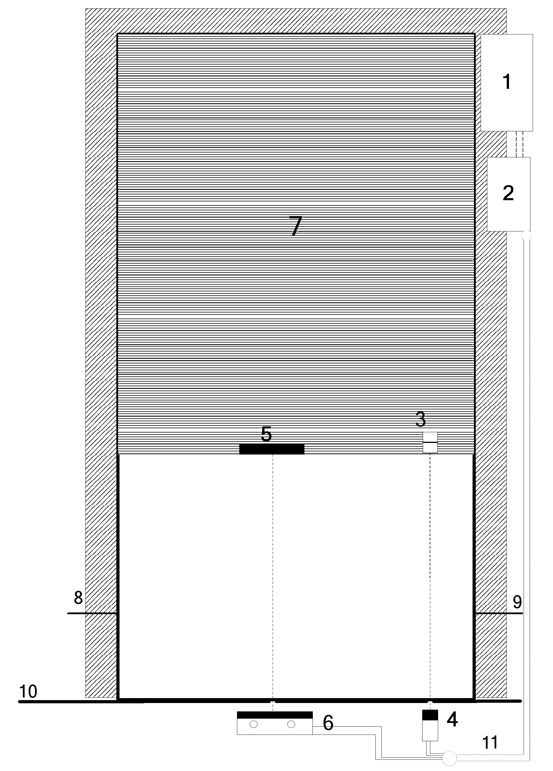
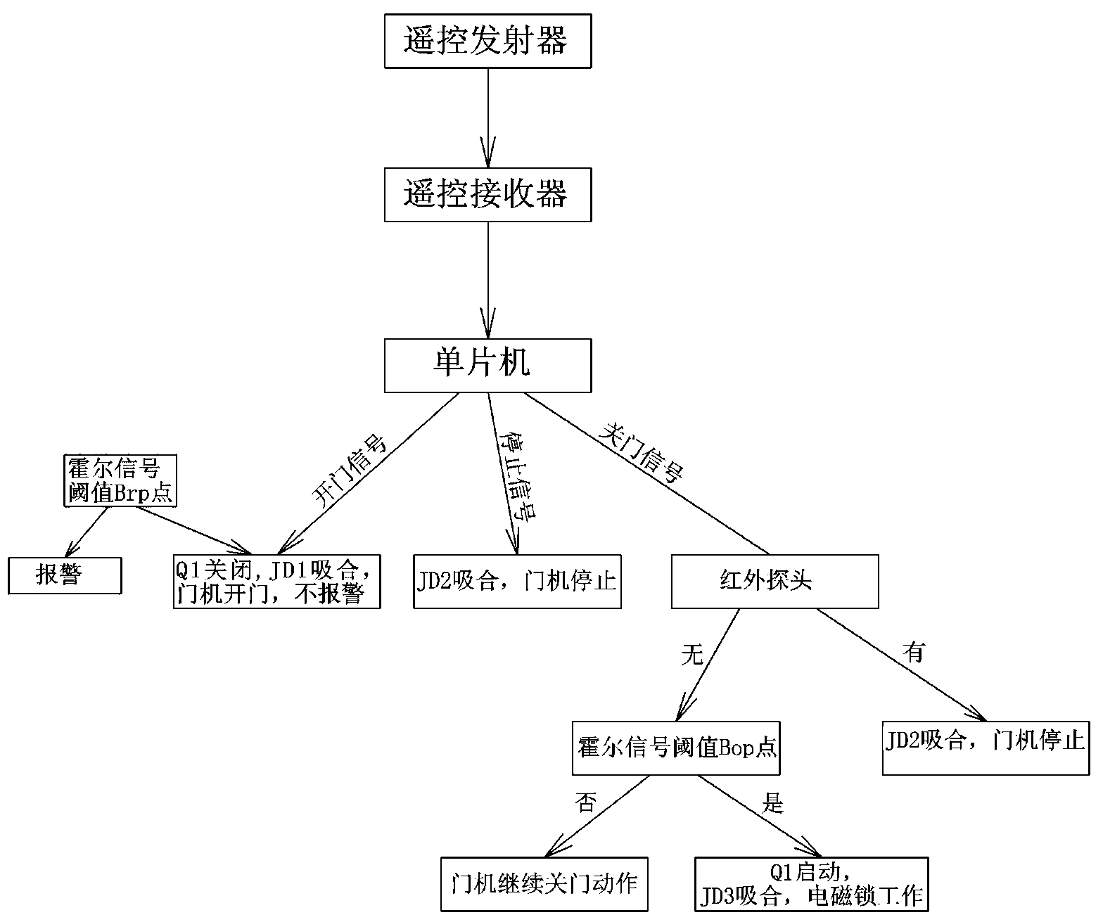
[0023] Embodiment one: see figure 1 and Figure 5 , the electromagnetic lock is fixed on the ground, and the lower edge of the rolling shutter door is fixed with an iron plate 5. The rolling door machine is installed on one side of the reel and closed, and the control chip is installed near the motor or hidden in the box near the wall. The control line of the electric control lock is connected to the output terminal of the control chip U1 after being connected through the PNP Darlington tube Q1. At the same time, a lower limit probe is set on the ground. The lower limit probe in this embodiment adopts a Hall switch, and a magnet is set on the lower edge of the rolling shutter door, and the two form an induction system. The signal end of the Hall probe is connected to the cathode of the diode D3, the anode of the diode D3 is connected to the signal input end of the control chip U1 through the resistor R8, and the anode of the diode D3 is connected to the high level through th...

Embodiment 2

[0039] Embodiment two: see figure 1 and Figure 5 , the content is basically the same as that of Embodiment 1, and the similarities will not be repeated. The difference is that an infrared sensing module is provided, that is, infrared directing or reflective sensors are installed on both sides of the door frame close to the ground, and the infrared sensors on both sides are respectively installed. The signal line of the through-shooting or reflection sensor is connected with the input end of the control chip. If there is an obstacle under the door during the process of closing the door, the signal from the transmitter of the infrared probe CON4 will be blocked, and the receiving end of the infrared probe will send out a level signal. After the 4th pin of the microcontroller detects the output signal of the infrared probe , will send a high-level signal to pin 14, drive the relay JD2 to pull in, and the door movement will stop.

Embodiment 3

[0040] Embodiment three: see figure 2 and Figure 5 , the content is basically the same as that of Embodiment 1, and the similarities will not be repeated. The difference is that the automatic locking module includes an electric control lock and an electromagnetic induction unit. Lock 19, have the slot 18 that cooperates with electric mortise lock on the corresponding position on the door plate simultaneously, and electromagnetic induction unit is that magnet 3 is installed on the lower edge of rolling shutter door, and limit probe 4 is set on the ground directly below magnet simultaneously, and this limit probe 4 The signal terminal of the electric control lock is connected with the input terminal of the control chip U1, and the control terminal of the electric control lock is connected with the PNP Darlington tube Q1 and then connected with the output terminal of the control chip U1. This embodiment uses an electric mortise lock. When the door is closed to the fast bottom,...


PUM


Abstract

The invention relates to a remote control electric rolling door alternating-current motor control circuit with an automatic locking function. The circuit comprises a singlechip main control module, a door rolling machine action control module, a lower limit detection module, an automatic locking module, a backup power supply control module and a remote control receiver module, wherein an electric control lock and a limit probe are arranged between the ground and the lower edge of a rolling door; the limit probe is connected with the input end of a controller; the electric control lock is connected with the output end of the controller; the controller is connected with a remote control receiver and provided with a remote control transmitter; a door rolling machine of the rolling door is an alternating-current motor; the alternating-current motor is connected with the inversion output end of an uninterrupted power supply (UPS); and the control end of the alternating-current motor is connected with the output end of the controller. The door can be automatically locked and prevented from being artificially lifted or prized after being closed, so that safety performance is high; and a backup power supply is provided, so that the door still can be electrically opened and closed when a mains supply is cut off, and the circuit is more convenient to use.

Description

technical field [0001] The invention relates to a rolling shutter door control technology, in particular to a remote control electric rolling door AC motor control circuit with an automatic locking function. Background technique [0002] At present, the known control systems used on the market can realize the remote control electric door opening and closing function, but there are still many shortcomings and defects that have not been resolved. These defects mainly include: [0003] 1. For all electric rolling doors, when the door is closed to the end, due to the soft feature of the door, the door can be lifted from the bottom, thieves can enter, and the safety performance is poor; even some large doors cannot be lifted by hand. It can be pried up with a stick, and people can easily climb in, and the anti-theft safety performance is very poor. This is the known fatal shortcoming of the electric rolling shutter door in the door control industry, but it cannot be solved so f...

Claims


Application Information

Patent Timeline
Patent Type & Authority Patents(China)
IPC IPC(8): E05B47/00E05B65/00E06B9/86E06B9/68G08B13/08H02J9/06
Inventor 王守国王俊榜黄宏军
Owner 郑州新大陆智能科技有限公司
Why Eureka
Try Eureka