Variable valve timing control apparatus

A valve timing control and variable technology, applied to valve devices, engine components, machines/engines, etc., can solve problems such as difficulty in processing inner rotors, increased weight and cost of inner rotors, etc.

Inactive Publication Date: 2012-04-04
AISIN SEIKI KK
View PDF1 Cites 23 Cited by
  • Summary
  • Abstract
  • Description
  • Claims
  • Application Information

AI Technical Summary

Problems solved by technology

The use of high-strength materials to form the inner rotor makes further processing of the inner rotor difficult
In addition, the weight and cost of the inner rotor will increase

Method used


Image

  • Variable valve timing control apparatus
  • Variable valve timing control apparatus
  • Variable valve timing control apparatus

Examples


Embodiment Construction

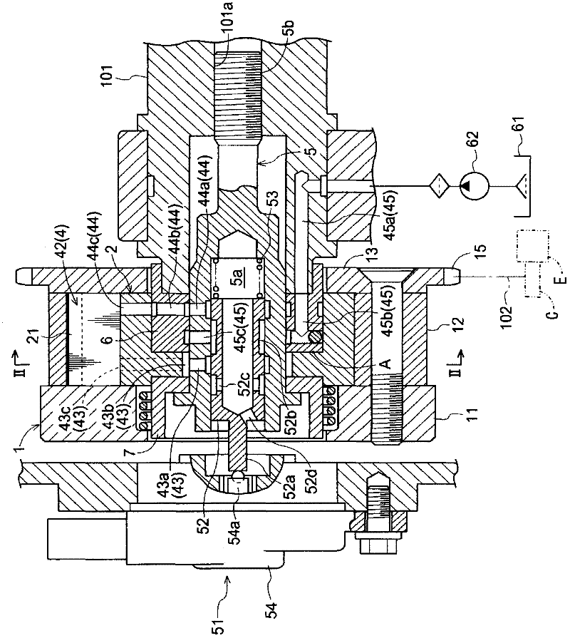
[0027] Next, a first embodiment and a second embodiment of the variable valve timing control device of the present invention will be described with reference to the drawings. In the first and second embodiments, the variable valve timing control device is arranged at the intake valve of the engine E of the vehicle. Each vehicle engine E in the first and second embodiments corresponds to an internal combustion engine.

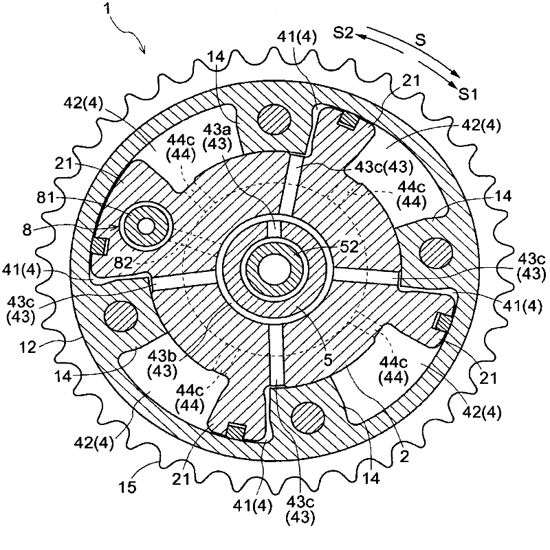
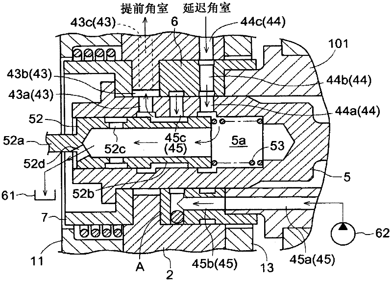
[0028] [overall structure] such as figure 1 As shown, the variable valve timing control device according to the first embodiment includes: a housing 1 which rotates synchronously with a crankshaft C as a drive shaft of an engine E; and an inner rotor 2 which is coaxially arranged with the housing 1, And can rotate relative to the housing 1. The intermediate member 6 is disposed between the inner rotor 2 and the bolt 5 as a driven shaft, and the rotation of the inner rotor 2 is transmitted to the bolt 5 (the bolt 5 is hereinafter referred to as an OCV bolt 5 )....


PUM


Abstract

A variable valve timing control apparatus, includes a housing (1) rotating in synchronization with a drive shaft (C) of an internal combustion engine (E), an inner rotor (2) arranged coaxially with the housing (1) and rotatable relative to the housing (1), a driven shaft (5, 101), an intermediate member (6) arranged between the inner rotor (2) and the driven shaft (5) and rotating in synchronization with the inner rotor (2) and the driven shaft (5), a first hydraulic fluid passage (43, 73), an inner room (43b, 73b) formed between the driven shaft (5) and the inner rotor (2) and constituting a portion of the first hydraulic fluid passage (43, 73), a second hydraulic fluid passage (44, 74), a passage (44b, 74b) formed in the intermediate member (6) and constituting a portion of the second hydraulic fluid passage (44, 74), and a contact portion (A, B) at which an axial surface of the intermediate member (6) is entirely in contact with the inner rotor (2) between the first hydraulic fluid passage (43) and the second hydraulic fluid passage (44).

Description

technical field [0001] The present invention generally relates to a variable valve timing control device. Background technique [0002] A known variable valve timing control device (cam timing device for an internal combustion engine) is disclosed in JP3965051B (hereinafter referred to as Patent Document 1). In this known variable valve timing control device, the inner rotor (inner body in Patent Document 1) is fixed to the camshaft with a shaft member such as a bolt (clamp screw in Patent Document 1). Two passages are formed between the inner rotor and the camshaft so that the two passages are separated from each other in the axial direction of the camshaft (rotation axis direction). [0003] According to the known variable valve timing control device as constructed in the above-mentioned Patent Document 1, the inner rotor and the shaft member need to be made of materials having substantially the same linear expansion coefficient in order to prevent the supply of oil to th...

Claims


Application Information

Patent Timeline
Patent Type & Authority Applications(China)
IPC IPC(8): F01L1/34
CPCF01L1/3442F01L2101/00F01L2001/34483F01L2001/34433F01L2301/00
Inventor 安达一成野口祐司朝日丈雄
Owner AISIN SEIKI KK
Why Eureka
Try Eureka