Lens barrel, imaging device and information terminal
A technology for mirror frames and support frames, applied in image communication, installation, instruments, etc., can solve the problems of cost increase, inability to miniaturize, large space, etc., and achieve the effect of preventing cost increase
- Summary
- Abstract
- Description
- Claims
- Application Information
AI Technical Summary
Problems solved by technology
Method used
Image

Examples
no. 1 approach
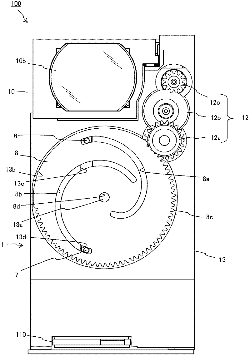
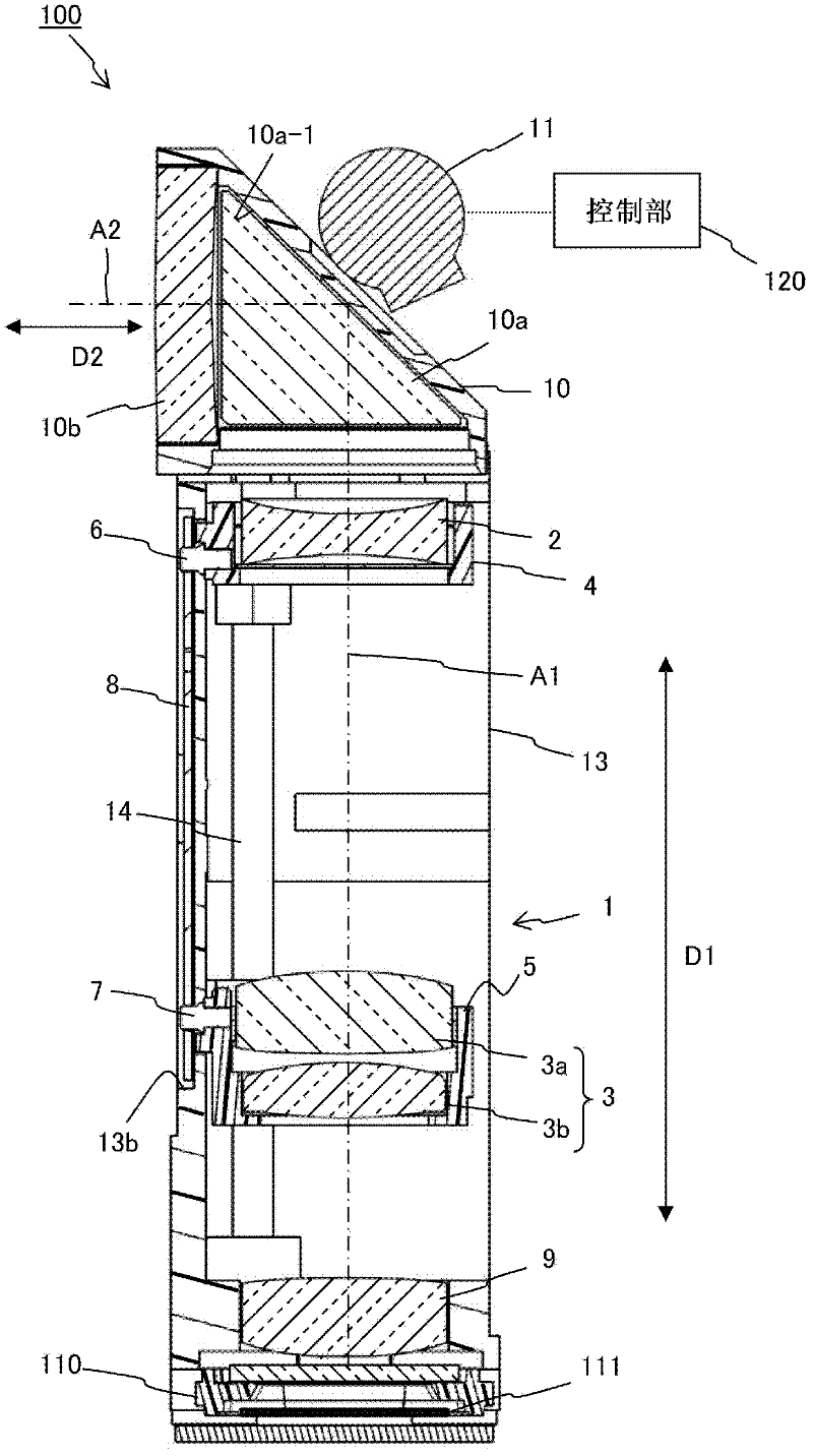
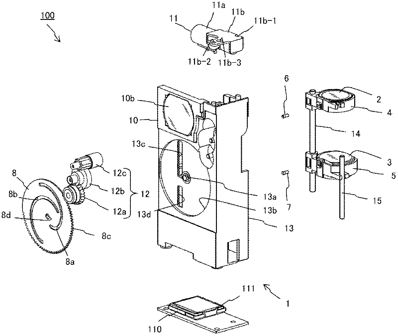
[0038] Such as Figure 1 to Figure 4 As shown, the imaging device 100 has: a lens frame 1; an imaging element substrate 110 having an imaging element 111 that receives light emitted from the lens frame 1 and outputs an imaging signal; and a control unit 120 that controls at least Frame 1 controls the zoom lens. The imaging device 100 is installed in communication equipment such as a mobile phone, or other electronic equipment, for example.
[0039] The lens frame 1 has: a first zoom lens 2, a second zoom lens 3 (3a, 3b), a first zoom lens support frame 4, a second zoom lens support frame 5, and a first cam pin (an example of a first protrusion) 6. A second cam pin (an example of a second convex portion) 7, a cam plate member (an example of a moving part) 8, an imaging lens 9, a curved lens having a prism (an example of a curved optical element) 10a and an incident lens 10b An optical system 10 , a drive unit 11 , a gear train 12 constituting a power transmission unit, a fixe...
no. 2 approach
[0090] Figure 5 It is a front view showing a schematic configuration of the imaging device 200 according to the second embodiment of the present invention.
[0091] Figure 6 It is a cross-sectional view showing a schematic configuration inside the imaging device 200 .
[0092] Figure 7 yes Figure 6 Enlarged view of part A.
[0093] Such as Figure 5 and Figure 6 As shown, the imaging device 200 has: a mirror frame 201; an imaging element substrate 110 having an imaging element 111 that receives light emitted from the mirror frame 201 and outputs an imaging signal; and a control unit 120 that controls at least The zoom lens of the mirror frame 201 is controlled. The imaging device 200 is installed, for example, in an information terminal such as a mobile phone, or in other electronic equipment.
[0094] The lens frame 201 has a first zoom lens 2 and a second zoom lens 3 (3a, 3b) as an example of a plurality of zoom lenses, a first zoom lens support frame 4 and a se...
no. 3 approach
[0158] Figure 11A and Figure 11B It is a front view and a rear view showing the information terminal according to the third embodiment of the present invention.
[0159] Figure 12 It is a schematic block diagram showing a control structure of an information terminal as an example of the above-mentioned information terminal.
[0160] Such as Figure 11A and Figure 11B As shown, the information terminal 400 includes the above-mentioned imaging devices 100, 200, and a control unit 120 (refer to figure 2 , Figure 6 ), a display unit 401 , a speaker 402 , a microphone 403 and an illumination unit 404 . Examples of the information terminal 400 include, for example, a mobile phone with a camera or a tablet (tablet), but are not limited thereto.
[0161] The control unit 120 controls each part of the control units 100 , 200 such as the drive unit 11 for moving the first zoom lens 2 and the second zoom lens 3 of the lens frames 101 and 201 , and the imaging element 111 , f...
PUM
 Abstract
Description
Claims
Application Information
 - Generate Ideas
- Intellectual Property
- Life Sciences
- Materials
- Tech Scout
- Unparalleled Data Quality
- Higher Quality Content
- 60% Fewer Hallucinations
Browse by: Latest US Patents, China's latest patents, Technical Efficacy Thesaurus, Application Domain, Technology Topic, Popular Technical Reports.
© 2025 PatSnap. All rights reserved.Legal|Privacy policy|Modern Slavery Act Transparency Statement|Sitemap|About US| Contact US: help@patsnap.com