Optical connector apparatus

An optical connector and connector technology, applied in the direction of instruments, connections where permanent deformation works, optics, etc., can solve the problem of not providing a cutout, and achieve the effects of reducing the elastic coefficient, reliable electrical connection, and reducing manufacturing costs.

Active Publication Date: 2012-04-04
JAPAN AVIATION ELECTRONICS IND LTD
View PDF17 Cites 16 Cited by
  • Summary
  • Abstract
  • Description
  • Claims
  • Application Information

AI Technical Summary

Problems solved by technology

None of the connecting members disclosed in the above-mentioned documents is provided with a notch

Method used


Image

  • Optical connector apparatus
  • Optical connector apparatus
  • Optical connector apparatus

Examples


no. 1 approach

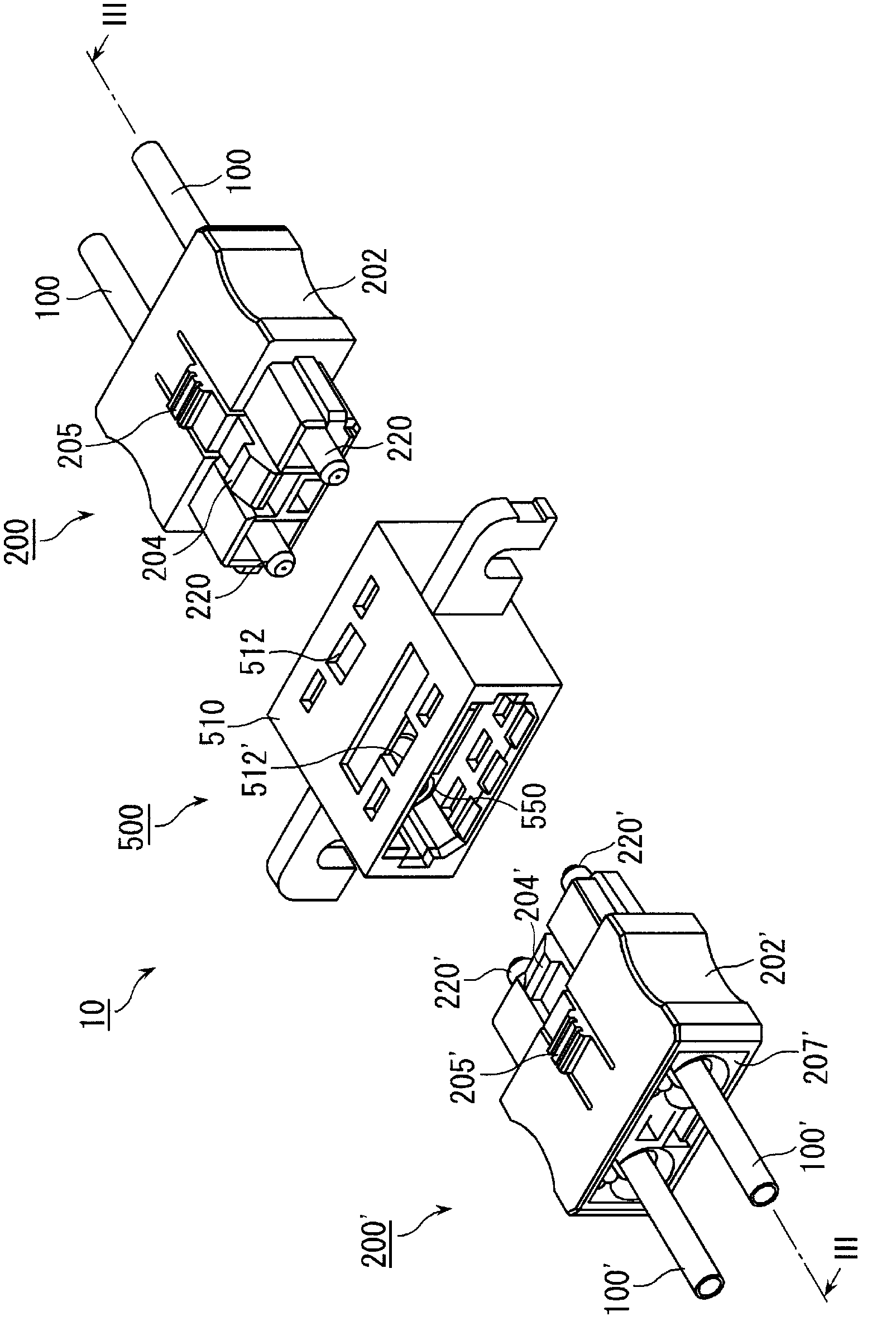
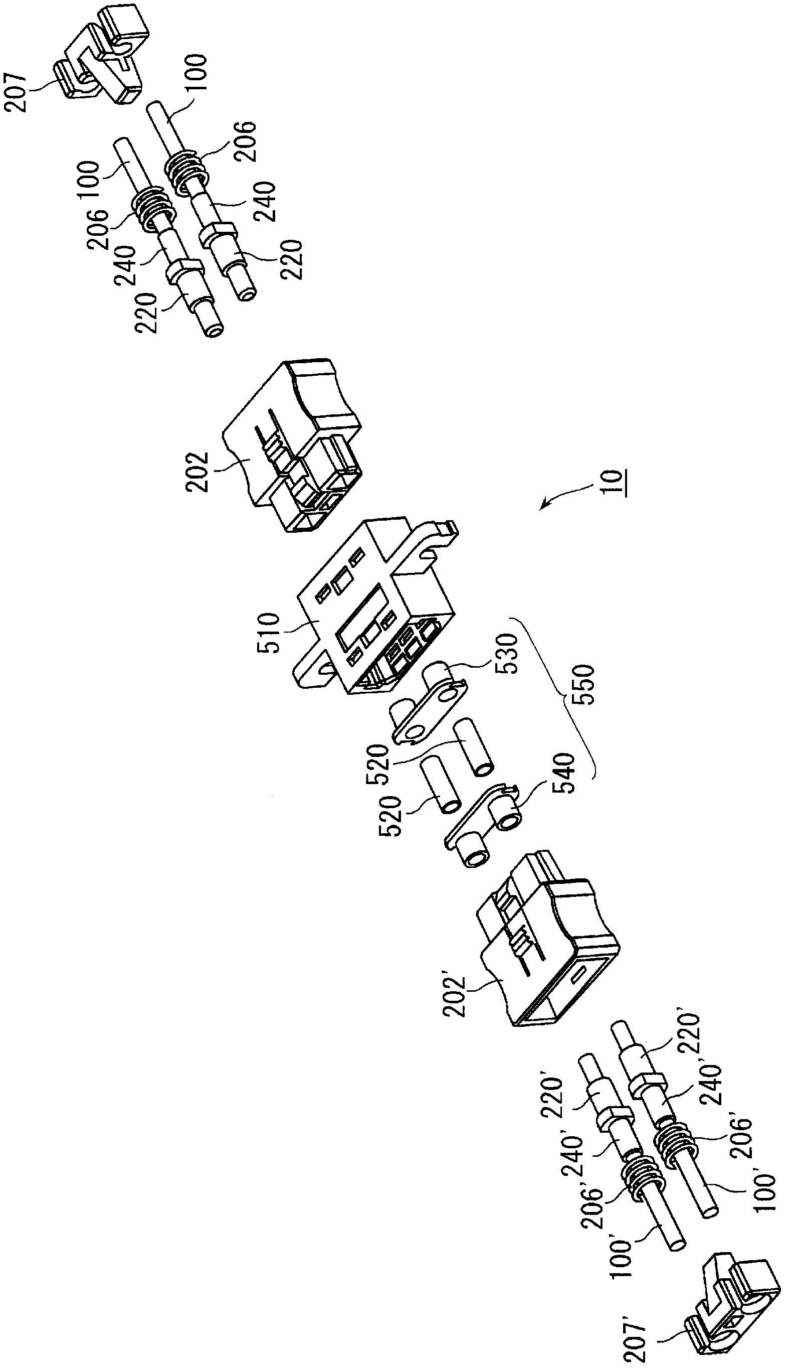
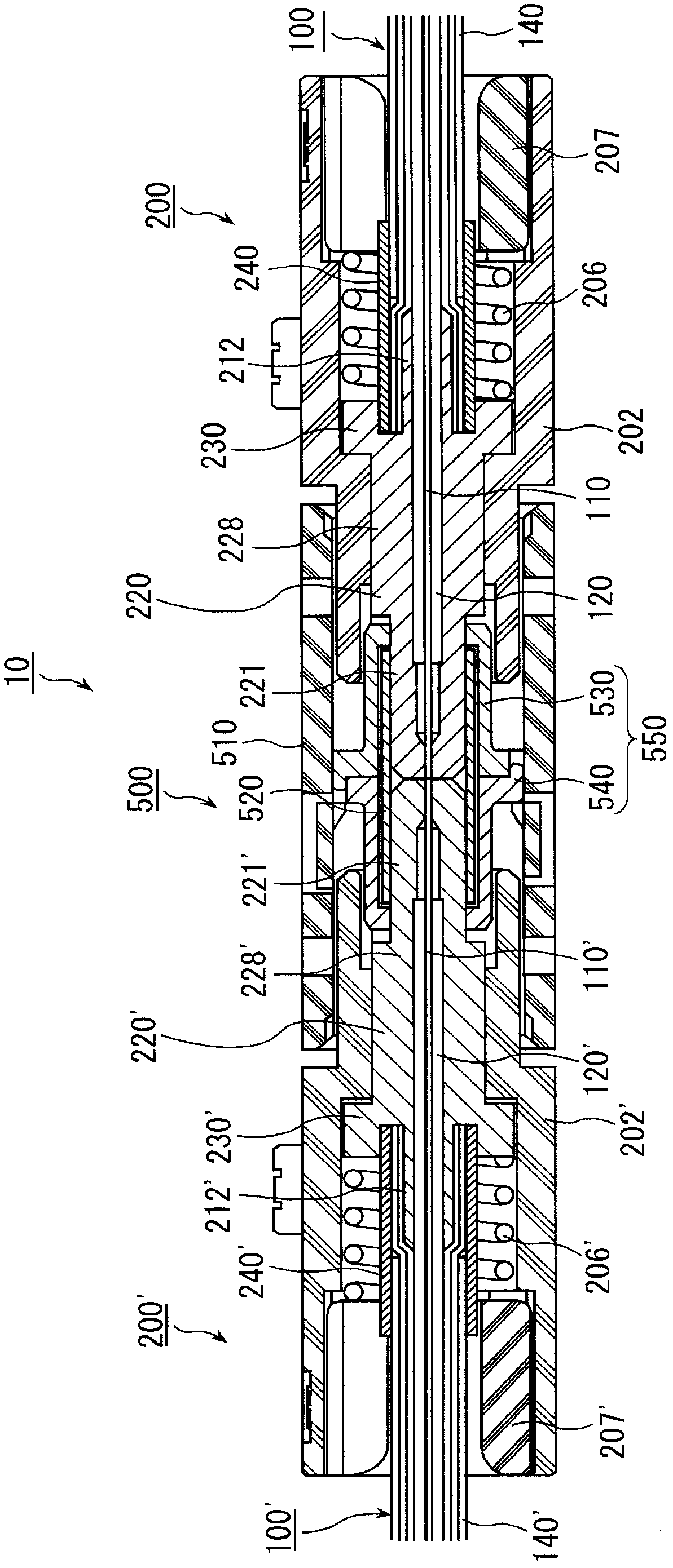
[0092] The optical connector device according to the first embodiment of the present invention is a device in which both ferrules are connected by being held by a connecting member. As a first embodiment, an optical connector device including two connectors and an adapter that relays them will be described. Such as Figure 1 to Figure 3 As shown, the optical connector device 10 has: a first connector 200 connected to the first photoelectric composite cable 100; a second connector 200' connected to the second photoelectric composite cable 100'; The adapter 500 relays the connection with the second connector 200'.

[0093] Such as image 3 As shown, the first connector 200 according to this embodiment includes a first ferrule 220 , and the first ferrule 220 is connected to the first photoelectric composite cable 100 . In addition, the second connector 200' has a second ferrule 220', and the second ferrule 220' is connected to the first photoelectric composite cable 100'. Her...

no. 2 approach

[0167] The optical connector device according to the first embodiment described above is a device for connecting an optoelectronic composite connector to another optoelectronic composite connector via an adapter, but the object to be connected via an adapter may be an optical element such as a photodiode.

[0168] like Figure 34 As shown, the optical connector device according to the second embodiment of the present invention includes a ferrule 220 connected to the photoelectric composite cable 100 , an optical element 800 such as a photodiode, and a housing 810 holding the optical element 800 . Here, the photoelectric composite cable 100 has the same structure as the photoelectric composite cable in the first embodiment, and the ferrule 220 uses the metal type in the first embodiment (refer to image 3 ) of the ferrule. Therefore, the ferrule 220 in this embodiment also includes the connected portion 221, the large-diameter portion 228, the shoulder portion 230, and a cylin...

no. 3 approach

[0172] The optical connector device according to the above-mentioned second embodiment holds the optical element in the housing, but the optical element may also be held in the housing. Figure 35 Adapter 900 as shown. Hereinafter, as a third embodiment of the present invention, an optical connector device including a connector and an adapter that holds an optical element and relays connection between the connector and the optical element will be described. It should be noted that, as the connector connected to the adapter 900, for example, the first connector 200 according to the above-mentioned first embodiment (refer to figure 1 ). At this time, as the ferrule held by the first connector 200, the ferrule 220 (refer to Figure 14 ), ferrule 220a (refer to Figure 10 ), ferrule 220b (refer to Figure 12 ), so below, the details of the connector and the ferrule are omitted, and only the adapter and the connecting member held by it are described.

[0173] like Figure 35 ...


PUM


Abstract

Disclosed is an optical connector apparatus comprising a connector which is connected to an opto-electrical composite cable including an optical fiber strand and a metal conductor, and an object to be connected. The connector is provided with a ferrule which has a conductor portion on at least a part of the surface thereof. The object to be connected is provided with an electrically conductive connector member to be connected to the ferrule. The ferrule and the cable are connected by a caulking structure. When the ferrule is inserted in the connector member, the connector and the object to be connected are electrically and optically connected to each other. Provided is also an optical connector apparatus which comprises a connector having a plurality of ferrules having different distances between the ends of the ferrules and the conductor portion, so that the time at which the connection of the connector to the object to be connected is established differs, and thus the optical connector apparatus is capable of hot swapping. The object to be connected can be a combination of an adapter and a mating connector, or an optical element and an adapter which holds the same, etc.

Description

technical field [0001] The present invention relates to an optical connector device, in particular to a wiring structure including a photoelectric composite cable and a ferrule, a connector connected to the photoelectric composite cable, and a connector for connecting the connector and the object to be connected (the opposite connector or Optical connector devices including adapters for relaying the connection of optical components, etc. Background technique [0002] As a connection structure between a photoelectric composite cable and a ferrule, Patent Document 1 to Patent Document 3 disclose, for example. The wiring method disclosed in the above document is the following method. First, a cylindrical member integrally formed with the ferrule (or prepared separately) is inserted between the optical fiber core wire and the tensile fiber. Next, the ferrule is fastened so that the tensile fiber and the sheath are interposed between the ferrule and the cylindrical member. The...

Claims


Application Information

Patent Timeline
Patent Type & Authority Applications(China)
IPC IPC(8): G02B6/38G02B6/42H01R13/46
CPCG02B6/3817G02B6/3825G02B6/3879G02B6/3893G02B6/3869G02B6/3855G02B6/3888C09K11/665G02B6/3821G02B6/3874H01R4/18G02B6/3877G02B6/4293
Inventor 岛津秀人桥口彻田中幸贵深山宪藏伊崎雅宏
Owner JAPAN AVIATION ELECTRONICS IND LTD
Why Eureka
Try Eureka