
Semi-forming centrifugal casting mould

A technology of centrifugal casting and casting molds, which is applied in the field of pouring machines, can solve the problems of large tool consumption, large machining allowance, labor and time-consuming, etc., and achieve the effects of saving materials, increasing yield, and reducing production costs

Inactive Publication Date: 2012-04-11
韦斌
View PDF0 Cites 5 Cited by
  • Summary
  • Abstract
  • Description
  • Claims
  • Application Information

AI Technical Summary

Problems solved by technology

[0002] At present, cylinder liner pouring machines at home and abroad are all straight pouring due to the limitation of mold release, the utilization rate of materials is only 1 / 3~1 / 2, the machining allowance is large, labor-intensive, time-consuming, tool consumption is also large, and the cost is high.

Method used


Image

  • Semi-forming centrifugal casting mould

Examples


Embodiment Construction

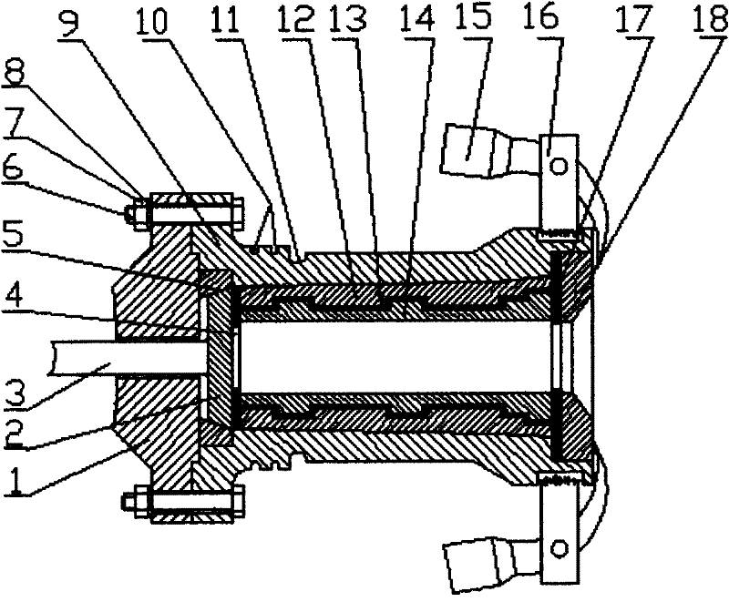
[0014] Such as figure 1 As shown, the casting mold includes a main shaft flange 1, a ejector plate 2, a ejector 3, a positioning plate 5, a bolt 6, a nut 7, a casting mold 9, a water tank 10, a water blocking tank 11, a flap forming sleeve 12, a fly Hammer 15 and stuffy cover 18, raise the positioning plate 5 at one end of the inner cavity of the casting mold 9 to install the ejector plate 5 with the ejector rod 3, the main shaft flange 1 is installed on the casting mold 9 through bolts 6 and nuts 7, and the casting mold 9 inner chambers are installed with flap-opening forming sleeves 12, and at the other end of the casting mold 9 inner chambers, a stuffy cover 18 is installed through a flyweight 15.

[0015] In the semi-formed centrifugal casting mold of the present invention, a water groove 10 and a water blocking groove 11 are arranged on the outer wall of the casting mold 9 .

[0016] In the semi-formed centrifugal casting mold of the present invention, the rear asbestos ...


PUM


Abstract

The invention discloses a semi-forming centrifugal casting mould. The casting mould comprises a main shaft flange plate (1), an ejector rod plate (2), a locating plate (5), a bolt (6), a nut (7), a casting mould (9), a sink (10), a water stop sink (11), an opening and forming sleeve (12), a fly hammer (15) and a blank cap (18), wherein the ejector rod plate (2) with an ejector rod (3) is installed at one end of the inner cavity of the casting mould (9) through the locating plate (5); the main shaft flange plate (1) is installed on the casting mould (9) through the bolt (6) and the nut (7); the opening and forming sleeve (12) is installed in the inner cavity of the casting mould (9); and the blank cap (18) is installed at the other end of the inner cavity of the casting mould (9) through the fly hammer (15). The semi-forming centrifugal casting mould is simple in structure, convenient to operate and capable of saving materials, reducing production cost and increasing the yield.

Description

technical field [0001] The invention relates to a casting machine, in particular to a semi-formed centrifugal casting mold. Background technique [0002] At present, the cylinder liner pouring machines at home and abroad are all straight casting due to the limitation of mold release, the utilization rate of materials is only 1 / 3~1 / 2, the machining allowance is large, labor-intensive, time-consuming, tool consumption is also large, and the cost is high. Contents of the invention [0003] The purpose of the present invention is to provide a semi-formed centrifugal casting mold, which can reduce machining allowance, save materials, reduce production cost, reduce environmental pollution and increase yield. [0004] The technical solution of the present invention is: the pouring mold includes a main shaft flange, a flap forming sleeve, a flyweight and a stuffy cover, and an ejector plate with an ejector rod is installed at one end of the inner cavity of the pouring mold through...

Claims


Application Information

Patent Timeline
IPC IPC(8): B22D13/10
Inventor 韦斌
Owner 韦斌
Learn More