Pneumatic clamping and self-locking device and method for clamping workpieces by using same

A self-locking device and pneumatic clamping technology, applied in auxiliary devices, auxiliary welding equipment, welding/cutting auxiliary equipment, etc., can solve problems such as injury to operators, burning of rotating parts, equipment damage, etc., to avoid accidents, Guaranteed reliability and small footprint

Inactive Publication Date: 2012-04-11
WUHU INST OF INSTR & METERS ANHUI PROV
View PDF14 Cites 17 Cited by
  • Summary
  • Abstract
  • Description
  • Claims
  • Application Information

AI Technical Summary

Problems solved by technology

[0002] In the assembly process of auto parts, the pneumatic flip clamping mechanism is generally used, but the common pneumatic flip clamping mechanism has obvious defects in the assembly process of some special parts, such as: for the spring assembly of the car seat, the glass assembly , Welding assembly and other production processes, in case of maintenance equipment, shift changes, sudden power outages, etc., the gas source will be automatically cut off
For ordinary pneumatic flip clamping mechanism, cutting off the air source will make the clamping mechanism automatically loosen or have no clamping force
And this phenomenon will cause

Method used


Image

  • Pneumatic clamping and self-locking device and method for clamping workpieces by using same
  • Pneumatic clamping and self-locking device and method for clamping workpieces by using same
  • Pneumatic clamping and self-locking device and method for clamping workpieces by using same

Examples


Embodiment Construction

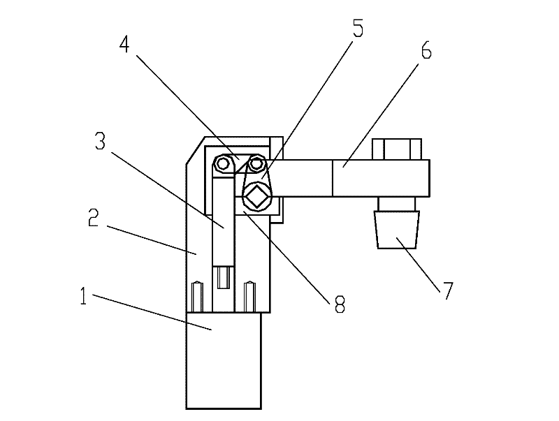
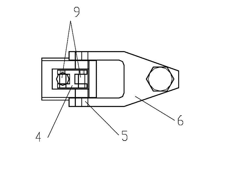
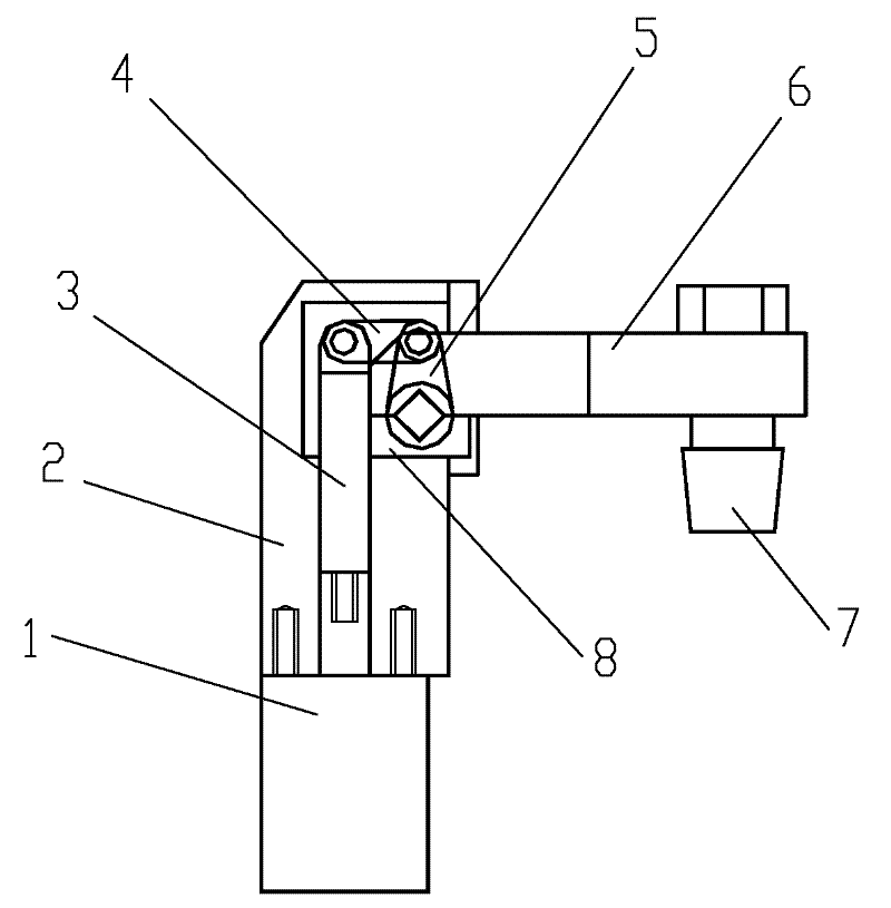
[0022] figure 1 It is a structural schematic diagram of the pneumatic clamping self-locking device of the present invention, figure 2 for figure 1 Schematic top view of the structure shown. Depend on Figure 1-2 Combining the shown structure, it can be seen that this kind of pneumatic clamping self-locking device includes a cylinder 1 fixed under the positioning seat 2. To connect, the other end of the first connecting rod 3 is connected with one end of the second connecting rod 4 through a threaded pin 9, and the threaded pin 9 is clearance fit with the holes on the first connecting rod 3 and the second connecting rod 4.

[0023] The other end of the second connecting rod 4 is connected with an end of the third connecting rod 5 by a threaded pin 9, the third connecting rod 5 is a crank connecting rod, the other end of the third connecting rod 5 is a crankshaft, and the crankshaft is connected to the positioning seat 2 The gaps on the upper and lower holes are matched, an...


PUM


Abstract

The invention discloses a pneumatic clamping and self-locking device and a method for clamping workpieces by using the same. The pneumatic clamping and self-locking device comprises an air cylinder fixed below a positioning seat, wherein the positioning seat is provided with a through hole; one end of a first connecting rod penetrates through the through hole and is in threaded connection with the air cylinder; the other end of the first connecting rod is connected with one end of a second connecting rod through a threaded pin; the other end of the second connecting rod is connected with one end of a third connecting rod through a threaded pin; the other end of the third connecting rod is in clearance fit with a hole on the positioning seat; a turning press plate is in threaded connection with square tenon clamping blocks at two sides of the turning press plate for clamping extending ends at two sides of the third connecting rod; the first connecting rod, the second connecting rod and the third connecting rod do a four-link motion; and a press head for clamping workpieces is arranged at the front end of the turning press plate. According to the pneumatic clamping and self-locking device with the structure, the clamping reliability is ensured and unexpected accidents caused by emergency are avoided; meanwhile, the whole four-link mechanism is designed in the positioning seat so as to avoid the damage to the clamping device, caused by welding splashing matters.

Description

technical field [0001] The invention relates to a pneumatic clamping self-locking device, in particular to a kind of assembly for some special parts on automobiles. Background technique [0002] In the assembly process of auto parts, the pneumatic flip clamping mechanism is generally used, but the common pneumatic flip clamping mechanism has obvious defects in the assembly process of some special parts, such as: for the spring assembly of the car seat, the glass assembly , Welding assembly and other production processes, in case of maintenance equipment, shift change, sudden power failure, etc., the gas source will be automatically cut off. For the ordinary pneumatic flip clamping mechanism, cutting off the air source will cause the clamping mechanism to automatically loosen or have no clamping force. And this phenomenon will cause the unassembled spring to pop out during the spring assembly process of the seat, thereby damaging the equipment or injuring the operator; it wi...

Claims


Application Information

Patent Timeline
IPC IPC(8): B23K37/04
Inventor 车灿吴进进乐志平罗旻洪平王洪礼卞宗越
Owner WUHU INST OF INSTR & METERS ANHUI PROV
Why Eureka
Try Eureka