Downhole safety valve

A technology of safety valve and valve body, which is applied in the direction of wellbore/well valve device, wellbore/well parts, earthwork drilling and mining, etc. It can solve the problem of limited number of uses, difficulty in meeting ultra-deep installation, sealing surface jamming, etc. Problems, to achieve the effect of increasing the number of uses and life

Active Publication Date: 2012-04-11
CHINA NAT OFFSHORE OIL CORP +2
View PDF5 Cites 19 Cited by
  • Summary
  • Abstract
  • Description
  • Claims
  • Application Information

AI Technical Summary

Problems solved by technology

[0008] 1) At present, the downhole safety valves in the world either adopt a piston structure or a sliding mandrel structure to push the valve plate to open and close. Both structures must be sealed by seals, which will bring the following disadvantages: a) Unable to withstand high temperature; b) Once the sand and dust in the well enters the sealing surface, it may cause jamming; c) Repeated opening and closing may cause damage to the seal, so the number of uses is limited
[0009] 2) Due to the limited spring force of the traditional downhole safety valve, and the cross-sectional area of ​​the piston or sliding mandrel cannot be too small due to the stability of the rod, the opening and closing pressure cannot be too high, so it is difficult to meet the requirements of ultra-deep installation.
This structure cannot get rid of the dependence on the tape, and the temperature will make the seal fail
[0011] 4) The static sealing problem of the body of the downhole safety valve at high temperature

Method used


Image

  • Downhole safety valve
  • Downhole safety valve
  • Downhole safety valve

Examples


Embodiment Construction

[0042] A downhole safety valve of the present invention will be described in detail below in conjunction with the embodiments and accompanying drawings.

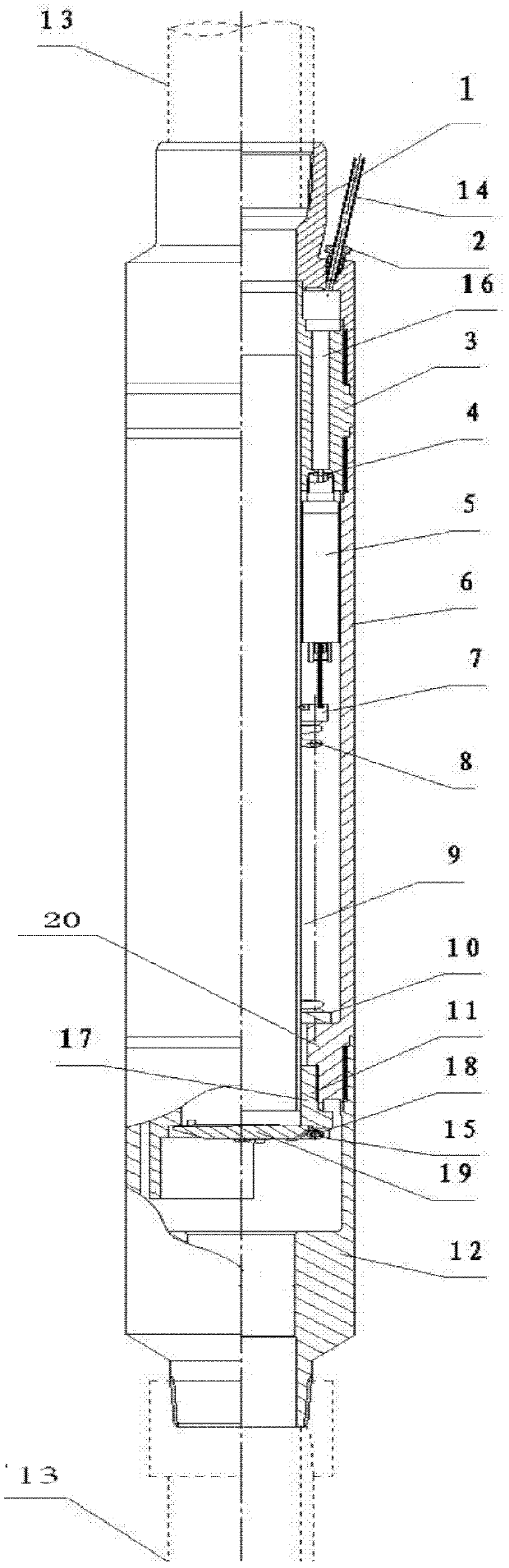
[0043] Such as figure 1 As shown, a downhole safety valve of the present invention includes a body consisting of a top joint 1, a valve body 3, an outer cylinder 6 and a tail joint 12 connected in sequence, and the material of the body is processed from a corresponding metal suitable for well conditions. As a result, the main body is the casing that connects the oil pipe and other moving parts.

[0044]A center pipe 9 is arranged in the body, the upper end of the top joint 1 and the lower end of the tail joint 12 are respectively connected to the external oil pipe 13, and a bellows is arranged in the gap between the outer cylinder 6 and the center pipe 9 Assembly 5, the bottom end of the bellows assembly 5 is connected to the positioning ring 7 fixed on the peripheral wall of the central tube 9, and the lower end of the pos...


PUM


Abstract

The invention discloses a downhole safety valve, wherein a central tube is arranged in a main body consisting of a top joint, a valve body, an outer cylinder and a tail joint connected sequentially; the upper end of the top joint and the lower end of the tail joint are respectively connected with an external oil tube; a corrugated tube assembly is arranged in the gap between the outer cylinder and the central tube, and the bottom end of the corrugated tube assembly is connected with a positioning ring fixed on the peripheral wall of the central tube; a boss is formed on the inner wall of the lower port of the outer cylinder, a pressure spring is sleeved on the periphery of the central tube between the lower side of the positioning ring and the boss, and a plate valve assembly is connected to the bottom end of the outer cylinder; the top joint is provided with a control line, the control line is embedded on the top joint through a control line connection assembly and communicated with a hydraulic oil passage formed in the valve body wall, and the bottom port of the hydraulic oil passage in the valve body wall is connected with the top end of the corrugated tube assembly. The downhole safety valve can be used in extreme environment with well conditions such as super high temperature steam thermal recovery, high gas tightness requirement, ultradeep installation, high sandiness environment and high corrosion.

Description

technical field [0001] The invention relates to a safety valve. In particular, it relates to a downhole safety valve used for well control of oil and gas wells in ultra-high temperature environments or other extreme well conditions. Background technique [0002] In the oil extraction industry, when performing downhole operations, the flow rate of hydrocarbon fluids often increases but cannot be controlled due to failure of extraction equipment and other reasons. At this time, it is necessary to close the channel in time to ensure operation safety and avoid greater accidents. In actual production, there must be a device (downhole safety valve) to close the fluid channel and realize the blocking function. [0003] Downhole safety valve is a kind of downhole equipment to prevent blowout and ensure production safety. In case of emergency, the oil and gas well can be shut down through the control pipeline connected from the valve body to the ground to release pressure and close...

Claims


Application Information

Patent Timeline
Patent Type & Authority Applications(China)
IPC IPC(8): E21B34/06
Inventor 陈舟圣刘志龙赵中奇
Owner CHINA NAT OFFSHORE OIL CORP
Why Eureka
Try Eureka