Sealing apparatus

A technology of sealing device and sealing components, applied in the direction of engine sealing, engine components, mechanical equipment, etc., can solve the problems of pressure rise, pressure leakage, bad sealing effect, etc.

Active Publication Date: 2012-04-11
ADVICS CO LTD
View PDF6 Cites 4 Cited by
  • Summary
  • Abstract
  • Description
  • Claims
  • Application Information

AI Technical Summary

Problems solved by technology

[0005] However, when the seal member moves in the axial direction of the drive shaft, pumping due to the movement occurs, and there is a possibility that a gap between the seal member and the drive shaft occurs in the gap between the housing and the drive shaft. Pressure rise in the area between the oil seals with associated pressure leakage and / or adverse effects on tightness

Method used


Image

  • Sealing apparatus
  • Sealing apparatus
  • Sealing apparatus

Examples


no. 1 approach

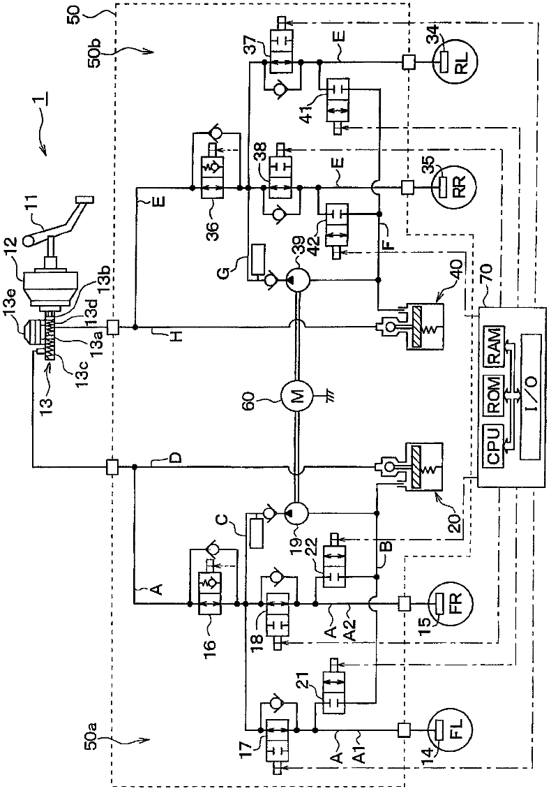
[0036] Hereinafter, the present invention will be described with reference to the embodiments shown in the drawings. figure 1 A schematic diagram of brake piping of a vehicle brake device to which a rotary pump device according to an embodiment of the present invention is applied is shown in . Below, based on figure 1 The basic configuration of a vehicle brake device will be described. Here, an example in which the brake device for a vehicle according to the present invention is applied to a vehicle constituting a hydraulic circuit of front and rear piping in a front-wheel drive four-wheeled vehicle will be described, but it can also be applied to a vehicle equipped with a right front X piping of each piping system of wheel-left rear wheel, left front wheel-right rear wheel, etc.

[0037] exist figure 1 Among them, when the driver steps on the brake pedal 11 , the stepping force is boosted by the booster 12 to push master pistons 13 a , 13 b arranged in a master cylinder (h...

no. 2 approach

[0109]A second embodiment of the present invention will be described. In this embodiment, the structure of the sealing member 130 is changed from that of the first embodiment, and other than that, it is the same as the first embodiment, so only the parts different from the first embodiment will be described.

[0110] Figure 7 It is a partially enlarged view of the sealing member 130 according to this embodiment. In this figure, the resin ring 131 and the rubber cup 132 are shown in a separated state.

[0111] Such as Figure 7 As shown, in the present embodiment, the holding portion 132c included in the base portion 132a is not formed in a cross-sectional arc shape, but is formed in a cross-sectional triangular shape. Moreover, the shape of the holding part accommodation part 131g formed in the resin ring 131 is also formed in the cross-sectional triangle shape corresponding to the holding part 132c.

[0112] In this way, even when the holding portion 132c is formed in a ...

no. 3 approach

[0116] A third embodiment of the present invention will be described. This embodiment is also obtained by changing the structure of the sealing member 130 from the first embodiment, and is the same as the first embodiment except for that, so only the parts different from the first embodiment will be described.

[0117] Figure 9 It is a partially enlarged view of the sealing member 130 according to this embodiment. In this figure, the resin ring 131 and the rubber cup 132 are shown in a separated state.

[0118] Such as Figure 9 As shown, in this embodiment, like the second embodiment, the holding portion 132c included in the base portion 132a is formed in a triangular cross-sectional shape, but the portion of the holding portion 132c on the oil seal 140 side is formed into a tapered surface. The groove slope 131e formed in the holding portion housing portion 131g of the resin ring 131 is also formed in a portion of the bottom surface 131d continuous with the wall surface ...


PUM


Abstract

The invention provides a sealing apparatus capable of limiting axial movement of a sealing member disposed between a shaft and a housing. A rubber cup (132) of the sealing member (130) is configured to have a base portion (132a) and a lip portion (132b), wherein the lip portion (132b) is used for limiting flow of braking fluid from a first chamber to a second chamber; and the base portion (132a) is fixed to a prescribed position between a resin ring (131) and a third cylinder barrel (71c). Thus, the axial movement of the sealing member (130) between a driving shaft (54) serving as the shaft and the third cylinder barrel (71c) serving as one part of the housing can be limited. Therefore, the sealing apparatus is capable of preventing pumping caused by axial movement of the sealing member (130) on the driving shaft (54) and preventing pressure rise of the second chamber between the sealing member (130) and an oil seal (140), and pressure leakage and / or harmful effect on tightness following the pressure rise.

Description

technical field [0001] The present invention relates to a sealing device that arranges a sealing member including a resin ring and a rubber ring in a gap between a housing and a shaft inserted into the housing, and seals the resin ring with the shaft side, and is suitable for use in Examples include seals in rotary pumps. Background technique [0002] Conventionally, Patent Document 1 discloses a brake device including a rotary pump. In the rotary pump included in this braking device, a seal member having a resin ring and a rubber ring is arranged between a drive shaft (shaft) for driving the rotary pump and a casing housing the rotary pump, and the Sealing components to suppress brake fluid leakage between the drive shaft and housing. Specifically, the sealing member is arranged such that the resin ring is in contact with the drive shaft and the rubber ring is in contact with the housing side, and the resin ring is pressed against the drive shaft by the elastic force of t...

Claims


Application Information

Patent Timeline
Patent Type & Authority Applications(China)
IPC IPC(8): F16J15/32F16J15/16F16J15/3236F16J15/3252F16J15/3276
CPCF16J15/164F16J15/3236F16J15/3208F16J15/324F16J15/3252F16J15/3268
Inventor 冈村圭久田庆武
Owner ADVICS CO LTD
Why Eureka
Try Eureka