
Network video monitor data flow storage system

A network video monitoring and storage system technology, applied in the field of network video monitoring data stream storage system, can solve problems such as file writing errors, heavy application system maintenance workload, failure to restore connections, etc., and achieve simple data transmission and easy control and maintenance, reducing the effect of single point of failure

Active Publication Date: 2012-04-11
FENGHUO COMM SCI & TECH CO LTD
View PDF5 Cites 11 Cited by
  • Summary
  • Abstract
  • Description
  • Claims
  • Application Information

AI Technical Summary

Problems solved by technology

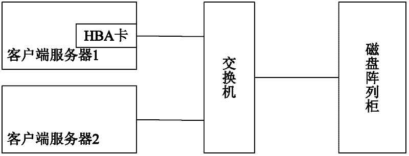
The separation of the application server and the disk array cabinet will increase the construction cost of the network storage system;
[0006] (2) At present, in the large-scale video surveillance industry, applications generally run on servers equipped with Linux or Unix operating systems. In the case of interruption, it will cause a file writing error, and the iSCSI-initiator software cannot restore the connection after the timeout expires. At this time, an error will occur in the file system, and the operating system will write the current If the attribute of the failed network disk is changed to read-only, the application program will no longer be able to write data to the network disk. Even if the network connection is restored later, it will still be unable to continue writing data, resulting in the data being unable to be saved, unless Manually repair the file system of the disk before continuing to write data to the disk
If the occurrence rate of such failures is high, the maintenance workload of the entire application system will be heavy

Method used


Image

  • Network video monitor data flow storage system
  • Network video monitor data flow storage system
  • Network video monitor data flow storage system

Examples


Embodiment Construction

[0032] In order to facilitate a further understanding of the structure and method of the present invention, preferred embodiments are described in detail below in conjunction with the accompanying drawings.

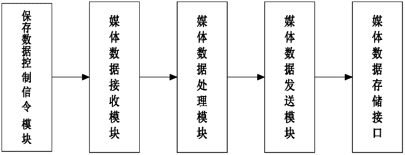
[0033] Such as figure 2 Shown, the network video surveillance data stream storage system that the present invention adopts, comprises client unit, server unit and physical disk unit, the client program of client unit and the server program of server unit pass standard API ( Application Program Interface, application program interface) for data transmission, and both the client unit and the server unit are embedded in the disk array cabinet to run.

[0034] The client unit is responsible for receiving data and processing it and sending it to the server unit, and requesting data from the server unit and analyzing it and sending it to the outside. The server unit is responsible for writing the data transmitted from the client unit into the physical disk unit of the disk ar...


PUM


Abstract

The invention discloses a network video monitor data flow storage system which comprises a client unit, a service terminal unit and a physical disk unit. A client program of the client unit and a service terminal program of the service terminal unit carry out media stream data transmission through a standard API interface, and the client unit and the service terminal unit are embedded into a disk array cabinet for operation. The client unit is responsible for receiving data, sending the data to the service terminal unit after processing, requesting data to the service terminal unit, and sending the data outward after parsing. The service terminal unit is responsible for writing the data sent by the client unit into the physical disk unit in the disk array cabinet according to a priority strategy, inquiring needed data in the physical disk unit, and sending the data to the client unit. According to the storage system in the invention, a single point fault in a data transmission process can be effectively reduced, and a data transmission mode becomes simpler and is easier to control and maintain.

Description

technical field [0001] The invention relates to a network video surveillance data stream storage system, in particular to a low-cost, high-reliability network video surveillance data stream storage system based on an IP-SAN disk array cabinet. Background technique [0002] At present, SAN (Storage Area Network, storage area network) storage is divided into FC-SAN (Fiber Channel-SAN, based on Fiber Channel protocol) and IP-SAN / NAS (Internet Protocol-SAN / NAS, based on Ethernet protocol), FC- SAN uses fiber optics and HBA (Host Bus Adapter, Host Bus Adapter) cards to transmit data. Although the performance is high, it is not widely used because of its high price; It is widely used due to its low price and high performance. In the network video surveillance industry, IP-SAN storage is generally used for massive video stream data storage. IP-SAN / NAS is divided into NAS (Network Attached Storage, network storage device) and iSCSI (Internet Small Computer System Interface, Interne...

Claims


Application Information

Patent Timeline
IPC IPC(8): H04N5/781H04N7/18
Inventor 周文举武树斌
Owner FENGHUO COMM SCI & TECH CO LTD
Learn More