
Method for realizing wireless network intelligent video monitoring system

A technology of intelligent video surveillance and wireless network, applied in the direction of closed-circuit television system, etc., can solve the problems of complex construction process, low network utilization rate, low degree of intelligence, etc., and achieve the effect of simplifying the construction process

Inactive Publication Date: 2012-04-11
SHANGHAI UNIV
View PDF5 Cites 36 Cited by
  • Summary
  • Abstract
  • Description
  • Claims
  • Application Information

AI Technical Summary

Problems solved by technology

[0003] Most of the existing video monitoring systems are mainly based on analog image information, which cannot meet the application requirements of real-time video monitoring. The degree of intelligence is low, and there are certain technical defects.
First, each channel of video needs to have its own independent transmission line, the network utilization rate is low, and there is a lot of bandwidth waste
Second, the video surveillance system often only realizes the real-time playback of images, requiring specialized personnel to keep watching the monitoring screen, the workload is heavy, and the system intelligence is not high
Third, the construction of the monitoring system needs to arrange special network lines, the construction process is complicated and the cost is high

Method used


Image

  • Method for realizing wireless network intelligent video monitoring system
  • Method for realizing wireless network intelligent video monitoring system
  • Method for realizing wireless network intelligent video monitoring system

Examples


Embodiment Construction

[0067] Below in conjunction with accompanying drawing, the implementation of the present invention is described in detail:

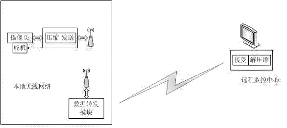
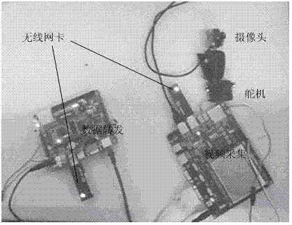
[0068] Such as figure 1 As shown, a wireless network intelligent video surveillance reference hardware system includes a USB camera, a video acquisition board, a data forwarding board, a monitoring center PC, and a steering gear.

[0069] The camera in the system completes the collection of video images, the video acquisition board completes the compression of video data and the execution of control commands, the data forwarding board completes the forwarding of video data and control commands, and the PC in the monitoring center completes data decompression and detection of moving objects. The steering gear controls the camera monitoring angle.

[0070] Such as figure 2 As shown, the experimental platform of the present invention is made up of two arm development boards, an embedded linux operating system (version 2.6.31) is transplante...


PUM


Abstract

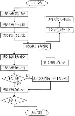
The invention provides a method for realizing a wireless network intelligent video monitoring system, which comprises the following steps: (1) real-time video acquisition; (2) video image coding and real-time transmission; (3) data forwarding; (4) video receiving, decompression and display; (5) motion object detection; and (6) optional angle adjustment of a camera. The invention can realize real time monitoring of a video monitoring system within a certain scope; the angle of the camera can be optionally adjusted according to the requirements of working personnel, thereby widening the video monitoring scope; and by adding the function of detecting and framing a motion object and the function of saving and recording a specific image, the intelligence of the monitoring system is enhanced, and the workload of the working personnel is reduced. In the invention, a video acquisition system is connected with a data forwarding module through wifi (wireless fidelity), and the data forwarding module is connected with the monitoring system through a public network, thereby simplifying the construction procedure of the system, lowering the construction cost of the system and improving the expandability of the system.

Description

technical field [0001] The invention belongs to the field of security technology, and in particular relates to a method for realizing a wireless network intelligent video monitoring system. Background technique [0002] In the past ten years, Internet technology and embedded technology have achieved rapid development. The Internet of Things based on the above two technologies has penetrated into various fields of daily life and production, improving the quality of production and life. A video monitoring technology integrating computer technology, network technology and digital video technology emerged as the times require. With the integration of automatic control, multimedia technology and 3G technology with video monitoring system, monitoring technology has also developed rapidly. The monitoring system uses the network to connect scattered and independent image collection points to achieve unified monitoring, unified management, and resource sharing across regions...

Claims


Application Information

Patent Timeline
Patent Type & Authority Applications(China)
IPC IPC(8): H04N7/18
Inventor 晁衍凯周勇飞杨永焕杨凤云徐昱琳岳天松
Owner SHANGHAI UNIV
Learn More