High-pressure pump

A technology of high-pressure pumps and pump pistons, applied in the field of fuel pumps, can solve problems such as expansion, increased leakage, leakage, etc., achieve high efficiency and avoid excessive leakage

Inactive Publication Date: 2012-04-11
ROBERT BOSCH GMBH
View PDF6 Cites 2 Cited by
  • Summary
  • Abstract
  • Description
  • Claims
  • Application Information

AI Technical Summary

Problems solved by technology

[0003] The high-pressure pump known from DE 10 2005 046 670 A1 has the disadvantage that leakage occurs during operation due to the high pressure in the pump working chamber via the pump piston guide
Here, deformation of the pump piston and the cylinder bore, in which the pump piston is guided, results in an enlarged guide and thus increased leakage at elevated high pressures.

Method used


Image

  • High-pressure pump
  • High-pressure pump
  • High-pressure pump

Examples


Embodiment Construction

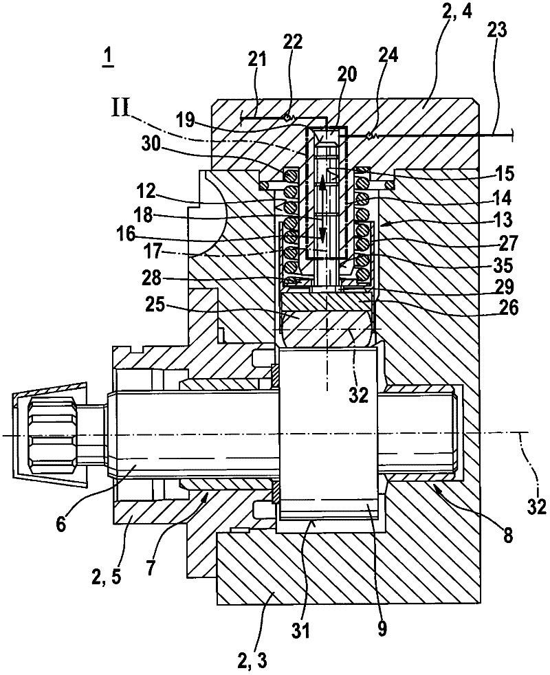
[0017] figure 1 According to an exemplary embodiment, a high-pressure pump 1 is shown in schematic axial section. The high-pressure pump 1 can be used in particular as a radial piston pump or an in-line piston pump for a fuel injection system of a compressed-air, self-ignition internal combustion engine. The high-pressure pump 1 is especially suitable for use in fuel injection systems having a fuel distribution plate which stores diesel under high pressure. However, the high-pressure pump according to the invention is also suitable for other applications.

[0018] The high-pressure pump 1 has a multi-part housing 2 . In this exemplary embodiment, the housing 2 consists of housing parts 3, 4, 5, wherein the housing part 3 represents the base body 3, the housing part 4 represents the cylinder head 4 and the housing part 5 represents the Flange 5.

[0019] The high-pressure pump 1 has a drive shaft 6 which is supported on the one hand at a bearing point 7 in the housing part ...


PUM


Abstract

A high-pressure pump (1), in particular serving as a radial piston pump or in-line piston pump for fuel injection systems of air-compressing auto-ignition internal combustion engines, has a pump assembly (13) and a driving shaft (6). The pump assembly (13) comprises a pump piston (16) guided in a cylinder bore (15) along an axis (17) of the cylinder bore (15), which can be driven by the driving shaft (6). Furthermore, a front surface (19) of the pump piston (16) in the cylinder bore (15) defines a pump working chamber (20). The pump piston (16) is made of a material which has an anisotropic elastic modulus. Thus having a high-pressure in the pump working chamber (20) causing the expansion of the cylinder bore (15), a radial deformation of the pump piston (16) can be reached, compensating the expansion of the cylinder bore (15).

Description

technical field [0001] The invention relates to a high-pressure pump, especially a radial piston pump or an in-line piston pump. The invention relates in particular to the field of fuel pumps for fuel injection systems of compressed-air, self-ignition internal combustion engines. Background technique [0002] A high-pressure pump for a fuel injection system of an internal combustion engine is known from DE 10 2005 046 670 A1. The known high-pressure pump has a multi-part pump housing, in which at least one pump element is arranged. The pump element comprises a pump piston driven by a drive shaft in a pump movement, which is guided displaceably in a cylinder bore of a part of the pump housing and delimits a pump working chamber in the cylinder bore. The pump piston is supported on the drive shaft via a hollow cylindrical hammer, wherein the hammer is guided displaceably in a bore in a part of the pump housing in the direction of the longitudinal axis of the pump piston. Du...

Claims


Application Information

Patent Timeline
Patent Type & Authority Applications(China)
IPC IPC(8): F02M63/02F02M59/02F02M59/44F04B1/04F04B53/00
CPCF02M59/02F04B1/0408F02M63/0265F02M59/445F05C2251/02
Inventor A・杜特
Owner ROBERT BOSCH GMBH
Why Eureka
Try Eureka