V-shaped turning tool and mounting tool post thereof

A technology of turning tool shank and turning tool, which is applied to woodworking lathes, wood turning tools, wood drilling tools, etc. The effect of increasing cutting amount and sharp cutting edge

Inactive Publication Date: 2014-04-30
林大伟
View PDF9 Cites 0 Cited by
  • Summary
  • Abstract
  • Description
  • Claims
  • Application Information

AI Technical Summary

Problems solved by technology

The stress of the turning tool is as follows: figure 1 As shown, the resultant force F is perpendicular or nearly perpendicular to the installation direction of the tool handle, and the direction of the resultant force F is just in the direction where the force on the tool handle is the weakest. The tool handle is prone to elastic deformation and vibration, which is very unfavorable to cutting and affects Precision

Method used


Image

  • V-shaped turning tool and mounting tool post thereof
  • V-shaped turning tool and mounting tool post thereof
  • V-shaped turning tool and mounting tool post thereof

Examples


Embodiment Construction

[0024] The following are the specific embodiments of the V-shaped turning tool, further describing the technical solution of the present invention, but the present invention is not limited to these embodiments.

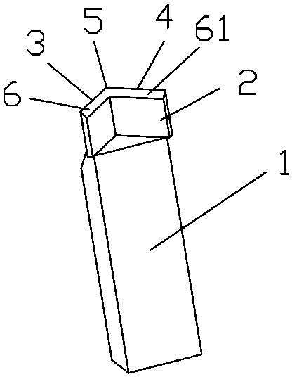
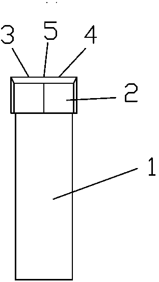
[0025] refer to Figure 2 to Figure 5 , in this embodiment, the V-shaped turning tool includes a handle 1, a V-shaped cutter head 2, and major and minor cutting edges 3 and 4 located on the cutter head 2, between the major and minor cutting edges 3 and 4 Intersect to form the tip 5, the main and minor cutting edges 3 and 4 are formed by the intersection of the front face 6 and the rear face 7, the minor front face 61 and the minor rear face 71 respectively, and the major and minor cutting edges 3 and 4 are located above the cutter head 2 , the knife handle 1 is connected with the bottom of the cutter head 2; the knife handle 1 is in the shape of a long prism.

[0026] The relief angle and the auxiliary relief angle of the turning tool are 0° to 15°, and its preferred...


PUM


Abstract

The invention discloses a V-shaped turning tool with a reasonable structure and capability of bearing higher cutting force and a mounting tool post thereof. The turning tool comprises a tool holder, a regular V-shaped tool bit and a primary cutting edge and an auxiliary cutting edge which are positioned on the tool bit, wherein the primary cutting edge and the auxiliary cutting edge are intersected to form a tool nose, are formed by intersecting a front side, a rear side, an auxiliary front side and an auxiliary rear side respectively, and are positioned on the upper side of the tool bit; and the tool holder is joined with the lower side of the tool bit. The tool bit has a regular V shape; the primary cutting edge and the auxiliary cutting edge are symmetrically distributed on both sides of the tool bit; and the properties of the primary cutting edge and the auxiliary cutting edge can be mutually exchanged according different movement directions during turning, namely the two edges can be changed into the primary cutting edge. In the V-shaped turning tool, the tool post for mounting the V-shaped turning tool is vertically arranged on a machine tool, the vertical turning tool mounting way is to mount the turning tool along a cutting force direction, and the forced direction of the tool holder is changed, so that impact force during cutting and the vibration of tool holder during cutting wood are reduced.

Description

technical field [0001] The invention relates to a woodworking lathe, in particular to a cutting tool on a woodworking lathe. Background technique [0002] At present, most woodworking lathes are designed with reference to metal lathes. The turning tool includes a handle, a cutter head and a cutting edge located at the front end of the cutter head. surface (usually a horizontal surface). The stress of the turning tool is as follows: figure 1 As shown, the resultant force F is perpendicular or nearly perpendicular to the installation direction of the tool handle, and the direction of the resultant force F is just in the direction where the force on the tool handle is the weakest. The tool handle is prone to elastic deformation and vibration, which is very unfavorable to cutting and affects Precision. Contents of the invention [0003] The problem to be solved by the present invention is to design a V-shaped turning tool and its mounting tool holder with a reasonable s...

Claims


Application Information

Patent Timeline
Patent Type & Authority Patents(China)
IPC IPC(8): B27G15/00B27C7/06
Inventor 林大伟
Owner 林大伟
Why Eureka
Try Eureka