
Power supply control method, device and system for alternating current (AC) drive electric locomotive train

A technology for power supply control and electric locomotives, which is applied to electric locomotives, locomotive propulsion methods, locomotives, etc., can solve the problems of lack of electric locomotives, affecting the safety of electric locomotive trains, and reducing the reliability of power supply control, and achieves the effect of improving reliability.

Active Publication Date: 2012-04-18
ZHUZHOU CSR TIMES ELECTRIC CO LTD
View PDF5 Cites 13 Cited by
  • Summary
  • Abstract
  • Description
  • Claims
  • Application Information

AI Technical Summary

Problems solved by technology

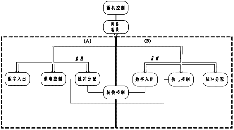
[0004] However, each subsystem in the existing power supply control device can only collect and process the digital and analog quantities and fault information of the components in this subsystem, but lacks the relevant components of the electric locomotive centralized control terminal, another subsystem Status information and bus equipment status information, when the relevant components of the electric locomotive centralized control terminal, another subsystem and / or bus equipment status information fail, the subsystem cannot respond in time, and a power supply failure will occur, which reduces the The reliability of power supply control, which further affects the safety of the electric locomotive train

Method used


Image

  • Power supply control method, device and system for alternating current (AC) drive electric locomotive train
  • Power supply control method, device and system for alternating current (AC) drive electric locomotive train
  • Power supply control method, device and system for alternating current (AC) drive electric locomotive train

Examples


Embodiment Construction

[0038] For reference and clarity, technical terms, abbreviations or abbreviations used hereinafter are summarized as follows:

[0039] DSP: Digital signal processor, a unique microprocessor, is a device that processes large amounts of information with digital signals. Not only is it programmable, but its real-time running speed can reach tens of millions of complex instruction programs per second, far exceeding that of general-purpose microprocessors. It is an increasingly important computer chip in the digital electronic world.

[0040] ARM: It is a RISC processor with high performance, low cost and low energy consumption. At present, it has been applied in various products such as industrial control, consumer electronics products, communication systems, network systems, and wireless systems.

[0041] FPGA: Feld-programmable gate array, Field Programmable Gate Array, which emerged as a semi-custom circuit in the field of application-specific integrated circuits, which not onl...


PUM


Abstract

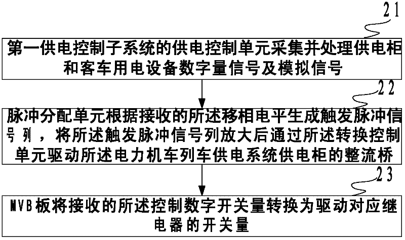
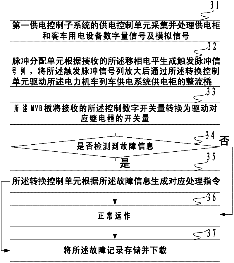
The embodiment of the invention discloses a power supply control method, device and system for an alternating current (AC) drive electric locomotive train. The power supply control device comprises a first power supply control subsystem and a second power supply control subsystem which are identical; the first power supply control subsystem is electrified to control a current power supply system of the electric locomotive train; the two subsystems are connected through a conversion control unit; each of the two subsystems comprises a power supply control unit, a pulse distribution unit and a multifunction vehicle bus (MVB) board; the power supply control unit of the first power supply control subsystem acquires and processes digital quantity signals and analogue signals of a power supply cabinet and passenger train electrical equipment, wherein the digital quantity signals and analogue signals are received and converted through an MVB by the MVB board. Through combining a data acquisition manner which integrates the MVB boards and the MVBs in the power supply control device with the original cold standby manner which carries out communication by using a bus, a condition if components related to an electric locomotive centralized control terminal, another subsystem and / or the state of passenger train equipment are broken down can be timely known, a response can be made, and thus, the reliability for power supply control is improved.

Description

technical field [0001] The present invention relates to the technical field of train power supply communication and control, and more specifically relates to a train power supply control method, device and system for an AC drive electric locomotive. Background technique [0002] The electric locomotive train power supply system is a system in which the electric locomotive itself provides the electric energy required for train air conditioning, heaters and lighting. The power supply system needs to be centrally controlled by the power supply control system to achieve reliable power supply. The existing train power supply control system for AC drive electric locomotives usually includes a train power supply cabinet and a centralized control terminal for electric locomotives, and each train power supply cabinet contains an independent train power supply control device. [0003] The train power supply control device includes two sets of identical power supply control subsystems,...

Claims


Application Information

Patent Timeline
IPC IPC(8): B61C3/00B60L9/00
CPCY02T10/7241Y02T10/72
Inventor 乔显华蔡杰李小平
Owner ZHUZHOU CSR TIMES ELECTRIC CO LTD
Learn More