

Transverse rigid rotor blade helicopter
A technology for rotor blades and helicopters, which is applied to rotorcraft, motor vehicles, aircraft parts, etc., can solve the problems of helicopter flight accidents, complicated helicopter manipulation, and complicated flight control, and achieves good maneuverability, high flight aerodynamic efficiency, and rotors. Dynamically simple effects
- Summary
- Abstract
- Description
- Claims
- Application Information
AI Technical Summary
Problems solved by technology
Method used
Image

Examples
Embodiment Construction
[0044]The accompanying drawings disclose the structural configuration of a preferred embodiment of the present invention without limitation, and the technical solutions of the present invention will be described in detail below in conjunction with the accompanying drawings.
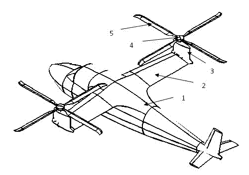
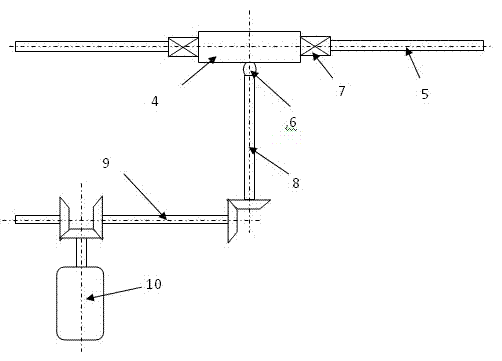
[0045] Such as figure 1 As shown, the tandem rigid rotor blade helicopter of the new configuration of the present invention includes a fuselage 1, a wing 2, a pier 3, a main drive device 10 placed in the fuselage 1, and a main drive device 10 placed in the wing Power transmission shaft 9, rotor drive shaft 8 placed in the pier, universal joint 6, hub 4, axial hinge 7, blade 5. The wing end is fixedly connected with the wing pier. The propeller hub, the axial hinge, and the blades form the rotor, and the axial hinge controls the blades to perform axial variable pitch motion. The rotor has no conventional flapping hinges and shimmy hinges, and the blades do not perform flapping and shimmy motions, so the...
PUM
 Abstract
Description
Claims
Application Information