Apparatus for fixing steel wire of wale

A steel wire fixing and cross bracing technology, which is applied in construction, excavation, infrastructure engineering, etc., can solve the problems of reducing the working efficiency of tensioning steel wires, increasing construction costs, and wasting materials, so as to reduce material consumption, prevent space reduction, reduce The effect of construction costs

Active Publication Date: 2014-05-14
SUPPORTEC CO LTD
View PDF3 Cites 0 Cited by
  • Summary
  • Abstract
  • Description
  • Claims
  • Application Information

AI Technical Summary

Problems solved by technology

Also, steel is used to withstand earth pressure in corners, wasting material and increasing construction costs
The steel reduces the space in the excavated planar structure, which reduces the work efficiency when tensioning the wires after fixing the wires of the prestressed cross braces

Method used


Image

  • Apparatus for fixing steel wire of wale
  • Apparatus for fixing steel wire of wale
  • Apparatus for fixing steel wire of wale

Examples


Embodiment 1

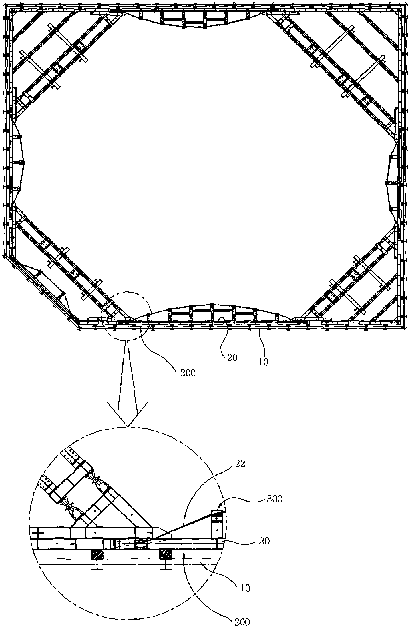
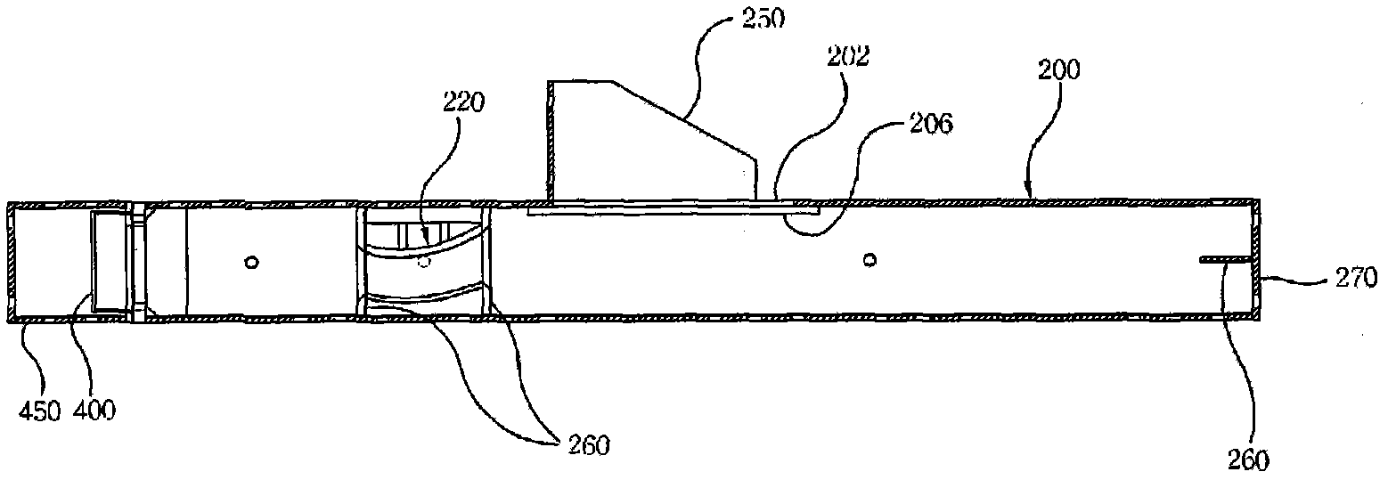
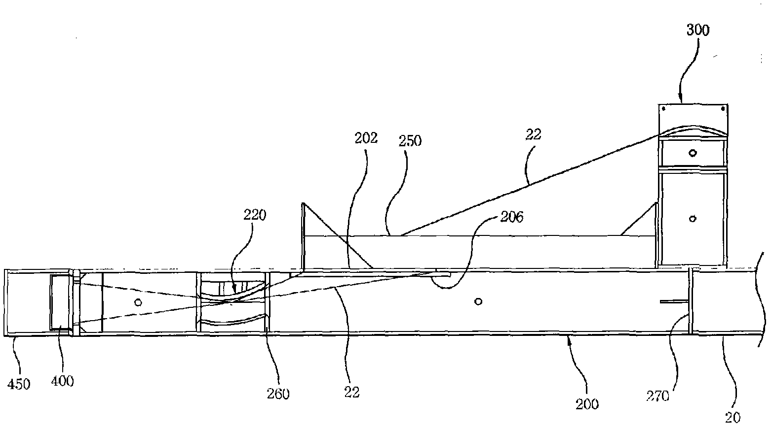
[0036] refer to Figure 1 to Figure 3 , according to the first embodiment of the present invention, the cross brace steel wire fixing device includes: a prestressed cross brace 20, which is integrally formed in front of the supporting wall 10, and has a tension force for tensioning the steel wire 22; a fixing body 200, Its first end is connected to one end of the cross brace 20 by bolts, and has a coupling hole 202, allowing the steel wire 22 to pass through the coupling hole 202; spacer 400, which is located at the second end of the fixed body 200, and fixes the inserted spacer 400 end of the wire 22;

[0037] In detail, the fixing body 200 is configured in the form of a beam integrated with and protruding from the end of the cross brace 20 , and a conventional wide I-beam is preferably used.

[0038] When using a wide I-beam as the fixing body 200, it is necessary to reinforce the flange of the beam having the coupling hole 202 so that the reinforcement plate 206 is mounted...

Embodiment 2

[0057] The following will refer to the attached Figures 6 to 10 A brace wire fixing device according to a second embodiment of the present invention will be described. The fixture includes a beam 610 connected to one end of a cross brace 520 for supporting the retaining wall 510 . The compression beam 620 is obliquely connected to one end of the beam 610 and integrated with at least one coupling beam 550 . The brace beam 630 is obliquely connected to one end of the compression beam 620 and one end of the cross beam 610 at the same time, thereby connecting the beams 610 and 620 to each other. A coupling hole 632 is formed in the brace beam 630 adjacent to the cross brace 520 and allows the steel wire 522 of the cross brace 520 to enter the hole 632 . The first and second spacers 710 and 720, respectively, are located in the triangle formed by the compression beam 620, the brace beam 630 and the cross beam 610, such that the first and second spacers 710 and 720 individually s...


PUM


Abstract

The present invention provides an apparatus for fixing a steel wire of a wale. In an embodiment, the present invention has an improved structure capable of fixing the steel wire of a prestressed wale at a location spaced apart from one end of the wale during pit excavation work for constructing an underground structure. The fixing apparatus prevents a sharp angle from being formed in the steel wire, and instead allows the steel wire to extend in the form of an arc shape, thus securing sufficient moment. The fixing apparatus provides strong reinforcement of parts to which high compressive force and high tensile force are applied. In another embodiment, the present invention has an improved structure capable of supporting a bracing beam and fixing and tensioning the steel wire in the bracing beam in corners during pit excavation work. At the corner, the fixing apparatus forms a triangular structure which can stably support the bracing beam and can fix and tension the steel wire at the same time, thus improving work efficiency. Further, the fixing apparatus has a simple structure, thus reducing the consumption of materials and reducing construction expenses.

Description

technical field [0001] In general, the present invention relates to a brace wire fixing device, and more particularly, to a brace wire fixing device which has a simple structure and can fix prestressed brace wires so that it can be Securely reinforce wires during excavation work on structures. Background technique [0002] During conventional digging work for constructing underground railways or building foundations, the ground is usually excavated in a predetermined area to a predetermined depth to dig a pit, and a required number of vertical piles are installed in the pit. [0003] After the vertical piles have been installed in the pit, a further section of the pit will be excavated and wide I-beams and liners will be installed in the pit. [0004] After the liner is installed in the pit, the work of constructing the underground railway or the foundation of the building will be advanced to continuous excavation, and repeated excavation is accompanied by repeated coupling...

Claims


Application Information

Patent Timeline
Patent Type & Authority Patents(China)
IPC IPC(8): E02D17/04
CPCE02D17/04
Inventor 白承德
Owner SUPPORTEC CO LTD
Why Eureka
Try Eureka