Variable pitch system for offshore high-power wind driven generator group and control method for variable pitch system

A wind turbine and pitch system technology, applied in the control of wind turbines, wind power generation, wind turbines, etc., can solve the problems of high cost of offshore wind power construction, complex hydraulic pitch drive structure, inability to solve the rotor axis, etc. Component failure risk, lifetime cost optimization, simple structure effect

Inactive Publication Date: 2012-04-18
DALIAN DESIGN INST CO LTD CHINA FIRST HEAVY IND +1
View PDF6 Cites 33 Cited by
  • Summary
  • Abstract
  • Description
  • Claims
  • Application Information

AI Technical Summary

Problems solved by technology

[0007] 1. The structure of the hydraulic variable pitch drive is complicated, there is oil leakage, various valve cores are easy to jam, the control accuracy is different in winter and spring, and maintenance is inconvenient, etc.
[0008] 2. DC motors require excitation current and a commutation device. There may be sparks during high-speed commutation, and the rotor is prone to heat, which requires regular maintenance, etc.
[0009] 3. The rotor of asynchronous motor is heated due to the existence of excitation current, the control method is complicated, and it is

Method used


Image

  • Variable pitch system for offshore high-power wind driven generator group and control method for variable pitch system
  • Variable pitch system for offshore high-power wind driven generator group and control method for variable pitch system
  • Variable pitch system for offshore high-power wind driven generator group and control method for variable pitch system

Examples


Embodiment Construction

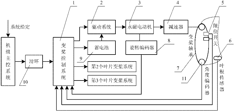
[0041] The present invention will be further described below in conjunction with the accompanying drawings. Such as figure 1 As shown, a pitch system for offshore high-power wind turbines includes an independent pitch drive system 2 on each blade, a pitch control system 1, a limit switch 5, an angle encoder 11 and a slip ring 10, The pitch drive system 2 is installed in the hub at the front of the nacelle, and its communication and power are realized through a slip ring 10 connected to the main control system in the nacelle; the pitch drive system 2 includes a drive system 2, a permanent Magnetic motor 3, reducer 4, blade root sensor 6, pitch bearing 7, encoder 8 and storage battery 9, described driving system 2 is connected with permanent magnet motor 3 through cable, and the output shaft of permanent magnet motor 3 is connected with reducer 4 is connected to the input shaft, the output pinion of the reducer 4 is meshed with the inner ring gear of the pitch bearing 7, the r...


PUM


Abstract

The invention discloses a variable pitch system for an offshore high-power wind driven generator group and a control method for the variable pitch system. The system comprises independent variable pitch driving systems on each blade, a variable pitch control system, a limit switch, an angular coder and a sliding ring, wherein the variable pitch driving systems are arranged in a hub on the front part of a cabin; the communication and the motive power of the variable pitch driving systems are realized through the sliding ring connected with the main control system in the cabin; and the variable pitch control system is used for allocating instructions from the main control system in the cabin to drivers and feeding back related signals detected by the angular coder, a rotation coder, the limit switch and a blade root sensor to the main control system in real time. In the variable pitch system, the force bearing acceleration sensor is arranged at a blade root and is used for detecting different applied forces of blades at different positions and feeding back to the variable pitch control system, and the variable pitch control system is used for sending a corresponding instruction to the driving systems, so that the size of a pitch angle is separately corrected, and the variable pitch system is completely independent.

Description

technical field [0001] The invention belongs to the driving automatic control technology of a wind power generating set, in particular to a pitch changing system and a control method for a large-power offshore wind generating set. Background technique [0002] Wind energy is the clean energy with the most mature technology and the most exploitable value in the renewable energy. While countries around the world are vigorously developing onshore wind power, they are also actively and steadily promoting the development of offshore wind power. The pitch system is the driving mechanism of a control system for optimal start-up and limiting and stabilizing the power output of the pitch wind turbine. [0003] At present, the pitch system used by onshore wind turbines can be divided into centralized pitch system and independent pitch system in terms of control methods, while offshore wind turbines mainly use independent pitch systems. Regardless of whether it is an onshore or offsh...

Claims


Application Information

Patent Timeline
IPC IPC(8): F03D7/00
CPCY02E10/723Y02E10/72
Inventor 方涛宋清玉黄维学高德忠
Owner DALIAN DESIGN INST CO LTD CHINA FIRST HEAVY IND
Why Eureka
Try Eureka