Spectral plane or focal plane installation and debugging method of hyperspectral imager

An installation and adjustment method and imager technology, which are applied in spectrum investigation and other directions, can solve the problems of position adjustment of CCD focal plane components, damage of CCD devices, complicated installation and adjustment process, etc., and achieve the effect of simple installation and adjustment process.

Inactive Publication Date: 2012-04-18
CHANGCHUN INST OF OPTICS FINE MECHANICS & PHYSICS CHINESE ACAD OF SCI
View PDF5 Cites 6 Cited by
  • Summary
  • Abstract
  • Description
  • Claims
  • Application Information

AI Technical Summary

Problems solved by technology

[0003] In order to solve the problem that the existing hyperspectral imaging system has complex assembly and adjustment process and cannot accurately adjust the position of the CCD focal plane a

Method used


Image

  • Spectral plane or focal plane installation and debugging method of hyperspectral imager
  • Spectral plane or focal plane installation and debugging method of hyperspectral imager
  • Spectral plane or focal plane installation and debugging method of hyperspectral imager

Examples


specific Embodiment approach 1

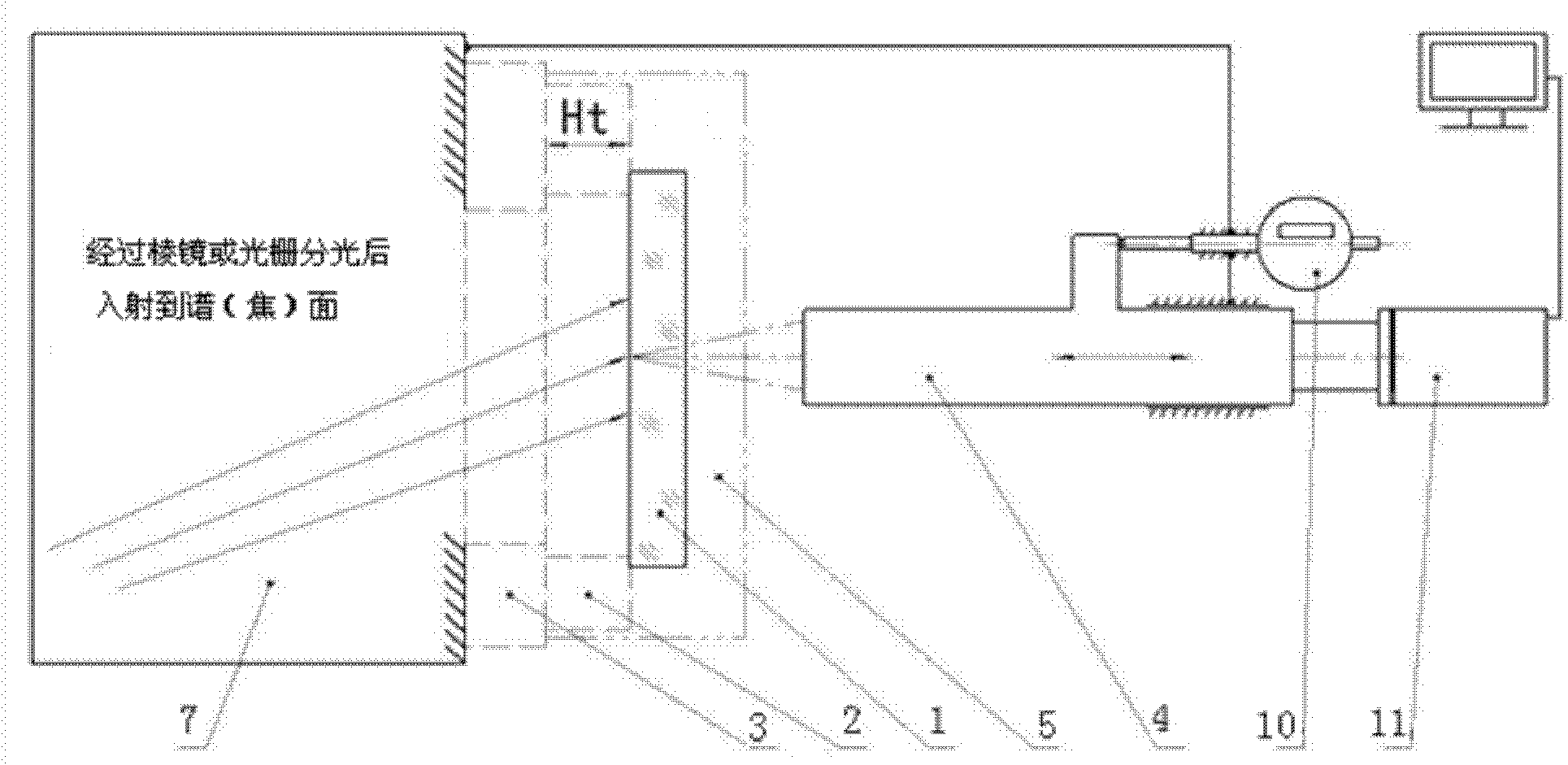
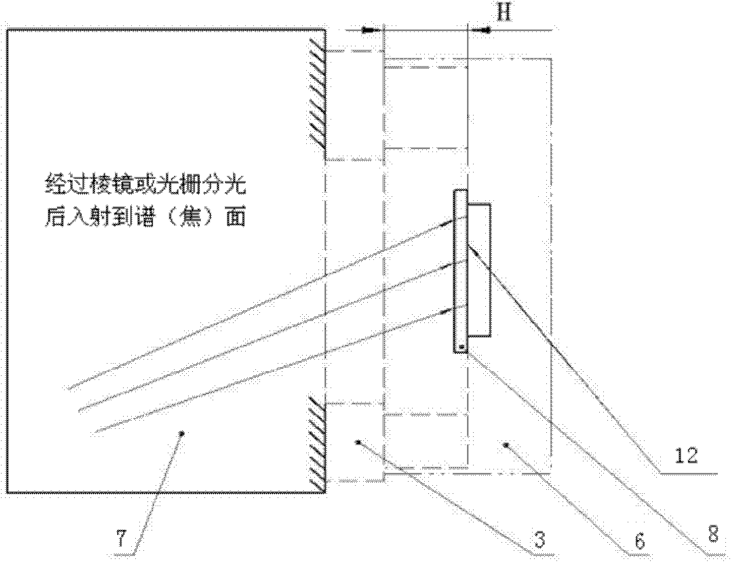
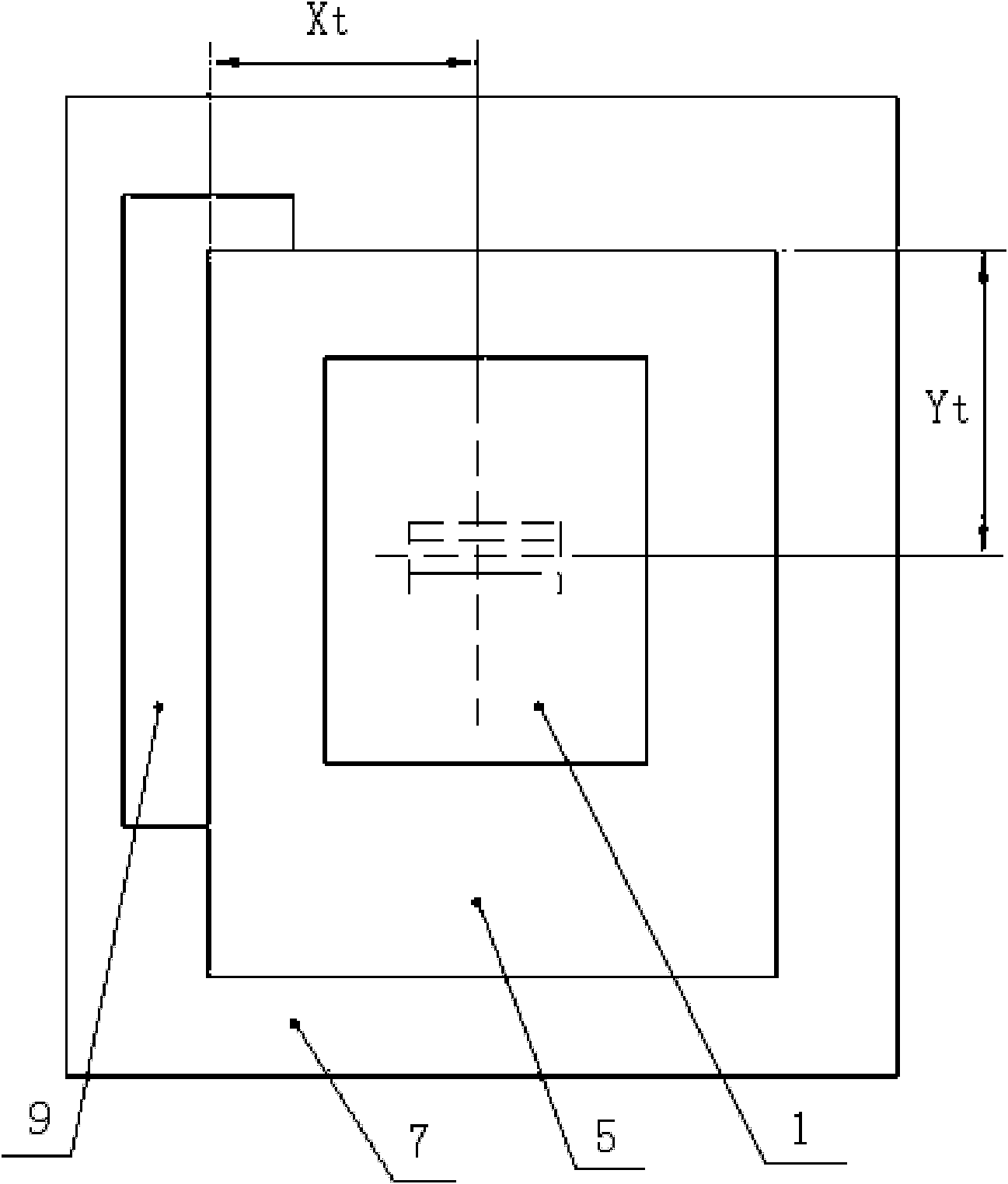
[0017] Specific implementation mode 1. Combination Figure 1 to Figure 6 To describe this embodiment,

[0018] First, the focal plane adjustment module 5 is according to the distance Ht=H, Xt=X, Yt=Y from the reference mounting surface of the CCD focal plane assembly 6 to the image plane of the hyperspectral imager 7, and Xt, Yt, and Ht are the focal plane mounting planes respectively. The length, width and height of the adjustment module 5, X, Y, and H are the length, width and height of the CCD focal plane assembly 6 respectively, and the position of the focal plane adjustment module 5 to the image plane of the hyperspectral imager 7 is in line with the CCD focal plane. The corresponding adjustment of the position of the surface assembly 6 to the position of the image plane of the hyperspectral imager 7; Image 6 , the CCD photosensitive surface 12 on the CCD focal plane assembly 6 coincides with the spectral surface of the hyperspectral imager 7, that is, the position of t...


PUM


Abstract

The invention relates to a spectral plane or focal plane installation and debugging method of a hyperspectral imager, relates to the field of imaging optical systems, and solves the problems that the existing hyper spectrometer imaging system is complex in the installation and debugging process and can not accurately adjust the position of a CCD (charge coupled device) focal plane component and frequent assembly and disassembly of the CCD focal plane component can easily result in damage to the CCD. The method comprises the following steps of: realizing equivalence between the position of a scribed line surface of a reticle in the bright background in a calibrated focal plane installation and debugging module and the position of a CCD light sensitive plane of the CCD focal plane component; replacing the CCD focal plane component by the installation and debugging module to debug an optical system; observing information, which is projected to the reticle by a camera, by using a microscope; figuring a CCD focal plane component adjustment pad to realize coincidence between a spectral line and the scribed line surface of the reticle; installing the CCD focal plane component and the calibrated CCD focal plane component adjustment pad in a matching mode; and replacing the installation and debugging module by the CCD focal plane component to finely adjust the position of the CCD focalplane. The method provided by the invention reduces frequent operations in the installation and debugging process of the CCD focal plane component and improves the reliability and stability of installation and debugging quality.

Description

technical field [0001] The invention relates to the field of imaging optical systems, in particular to a method for adjusting the spectral plane or focal plane of a hyperspectral imager. Background technique [0002] At present, the imaging system installation method is to place a piece of frosted glass or tracing paper at the focal plane of the CCD to observe the image projected on the frosted glass or tracing paper, similar to the viewfinder of an old-fashioned film camera such as a single-lens reflex Hasselblad The flat frosted glass of the viewfinder of the Brad 500C camera and the dual-lens reflex Seagull 4A-1 camera. This method uses the naked eye, a split image circle, or a magnifying glass to observe the clarity of the image. Because the frosted glass is opaque, it is impossible to use a microscope to accurately calibrate the normal direction, meridian, and sagittal direction of the spectral plane or focal plane, and it is impossible to accurately measure and adjust...

Claims


Application Information

Patent Timeline
IPC IPC(8): G01J3/28
Inventor 高志良
Owner CHANGCHUN INST OF OPTICS FINE MECHANICS & PHYSICS CHINESE ACAD OF SCI
Why Eureka
Try Eureka